
User Manual

gpelectric.com | [page 37]
3.7 FINAL INSPECTION
1.
Verify all cables / conduit runs are secured with zip ties or other non-conductive cable clamps to prevent damage from vibration.
2. Ensure all cables that pass through walls, bulkheads or any other openings are protected against abrasion by using strain
reliefs and/or grommets.
3. Check all AC, DC and ground connections are securely tightened, and if required covered with suitable anti-seizing grease.
4. Check the AC terminal connection cover plate has been securely re-attached.
5. Check all connections are secure in the main and sub panels - replace all covers.
6. If required by code, have the installation inspected by an electrical inspector.
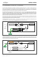
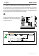
3.8 TESTING THE INSTALLATION
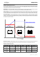
1. Apply battery power to the inverter by engaging the fuse, switching the breaker or switching the battery disconnect switch
to the ON position. The GP-IC-2000 will remain off.
2. Disconnect all AC loads from the breaker panel by switching the main on/off breaker to OFF.
3. Press the ON/OFF button. Verify the inverters status indicator is solid green (ON).
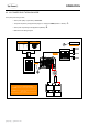
4. Connect a 25W light bulb to the inverter output and verify it comes on and shines normally.
5.
Press and release the ON/OFF button to turn the Inverter / Charger off, the bulb will turn off and the status indicator will turn off.
6. Apply AC shore power (utility or generator) to the GP-IC-2000. After around 10 seconds the Inverter / Charger will click and
the incoming power will be passed through and the light bulb will turn on. The status indicator will be green.
7. The inverter is currently OFF because the AC shore power is powering the light bulb. Press and release the ON/OFF switch
on the GP-IC-2000 to turn on the Inverter.
8. Disconnect the AC shore power, the light bulb should remain on and is now being powered by the Inverter (battery bank).
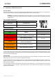
3.9 WARNING LABELS
When an Inverter / Charger is installed in a building the NEC requires a label or plaque to be provided. This label / plaque is
required to be easily visible and to provide information that informs users of the location of all electrical system disconnects.
Buildings with stand alone power systems (solar, generator) and utility power must have a permanent plaque or directory providing
the location of both system disconnects.
An Inverter warning label should be installed in a clearly visible location on the breaker panel that is being powered by the GP-
IC-2000. This label is used because it might be falsely assumed that the panel is no longer “live” after the AC Shore Power is
turned off, when power may actually still be available from the Inverter (battery bank) powering the sub panel.
INSTALLATION