
User Manual

[page 34] | gpelectric.com
120 VAC
50A
IN 1
AC Hot 1 from main panel
ACN-IN
AC Neutral from main panel
AC Ground
AC Ground from main panel
OUT 1
AC Live to sub panel
ACN-OUT
AC Neutral to sub panel
AC Ground
AC Ground to sub panel
Shore Power
120 VAC
Generator Power
120 VAC
120 VAC
Main Panel
Sub Panel
AC Terminal Block
240 VAC
50A
Shore Power
120/240 VAC
Generator Power
120/240 VAC
120 VAC
Main Panel
Sub Panel
IN 2
AC Hot 2 from main panel
IN 1
AC Hot 1 from main panel
ACN-IN
AC Neutral from main panel
OUT 1
AC Live to sub panel
ACN-OUT
AC Neutral to sub panel
AC Terminal Block
IN 2
AC Hot 2 from main panel
GP-IC-2000
AC Power
Source
Maximum
Input
Breaker
required
Minimum
Wire
Size
Maximum
Inverter
Pass
Through
Capacity
Hot 1 (Leg 1)
50A
(Single Pole Breaker)
Hot 2 (Leg 2)
50A
(Single Pole Breaker)
#6 AWG
(Input & Output)
50A
12000W
50A @ 120VAC (Hot 1)
50A @ 120VAC (Hot 2)
Note: Loads must be correctly balanced between both
phases (Hot 1 and Hot 2) on the breaker panels in order to
get maximum capacity
AC Power
Source
Maximum
Input
Breaker
required
Minimum
Wire
Size
Maximum
Inverter
Pass
Through
Capacity
#8 AWG
(Input & Output)
6000W
50A @ 120VAC (Hot 1 + Hot 2)
120 VAC
≤ 25 Amps a Leg
#6 AWG
#6 AWG
#8 AWG
#8 AWG
GFCI
Outlet
GFCI
Outlet
GFCI
Outlet
GFCI
Outlet
ACN-IN (White)
AC Neutral Input
ACN-OUT (Black)
AC Neutral to sub panel
GROUND
GP-IC-2000 Chassis Ground
GROUND
GP-IC-2000 Chassis Ground
AC Power from Utility or
Generator
ACN-IN (White)
AC Neutral Input
AC Power Source
Ground
AC Power Source
Ground
ACN-OUT (Black)
AC Neutral to sub panel
GROUND
GP-IC-2000 Chassis Ground
GROUND
GP-IC-2000 Chassis Ground
Main Chassis (RV, Boat)
Earth Ground
Main Chassis
Earth Ground
ACN-IN (White)
AC Neutral Input
ACN-OUT (Black)
AC Neutral to sub panel
GROUND
GP-IC-2000 Chassis Ground
GROUND
GP-IC-2000 Chassis Ground
AC Power from Utility or
Generator
AC Neutral to AC Source Ground
Transfer Relay Connected
AC Power Source
Ground
Main Chassis
Earth Ground
2
1
2
1
x
AC Neutral to Chassis
Ground - Permanently
Disabled
Screw Removed
AC Neutral to Chassis
Ground Disconnected
AC Neutral to AC Source Ground
Transfer Relay Connected
AC Neutral to AC Source Ground
Transfer Relay Disconnected
AC Neutral to Chassis
Ground Connected
Neutral Bus Bar
Ground Bus Bar
Neutral Bus Bar
Ground Bus Bar
Neutral Bus Bar
Ground Bus Bar
OUT 2
AC Live to sub panel
50A
(Single Pole Breaker)
Maximum 50A Breaker
(single pole)
AC Ground
AC Ground from main panel
AC Ground
AC Ground to sub panel
OUT 2
AC Live to sub panel
Neutral Bus Bar
Ground Bus Bar
Hot 1 (Black)
Hot 2 (Red)
External
Transfer Switch
(only required if using
a hardwired generator
and shore power)
External
Transfer Switch
(only required if using
a hardwired generator
and shore power)
Hot 1 (Black)
120 / 240 VAC
50 Amps per 120 VAC leg.
Hot 1 + Hot 2.
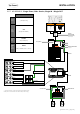
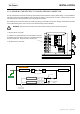
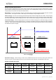
Split Phase - ≤50 Amp Service
Install Option 1
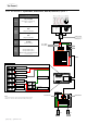
Single Phase - 30> Amp Service
GP-IC-2000
Notes:
* All previous converter / charger wiring must be disconnected from the
breaker panel. The GP-IC-2000 is now used for battery bank charging
Notes:
* All previous converter / charger wiring must be disconnected from the
breaker panel. The GP-IC-2000 is now used for battery bank charging
120 VAC
50A
IN 1
AC Hot 1 from main panel
ACN-IN
AC Neutral from main panel
AC Ground
AC Ground from main panel
OUT 1
AC Live to sub panel
ACN-OUT
AC Neutral to sub panel
AC Ground
AC Ground to sub panel
Shore Power
120 VAC
Generator Power
120 VAC
120 VAC
Main Panel
Sub Panel
AC Terminal Block
240 VAC
50A
Shore Power
120/240 VAC
Generator Power
120/240 VAC
120 VAC
Main Panel
Sub Panel
IN 2
AC Hot 2 from main panel
IN 1
AC Hot 1 from main panel
ACN-IN
AC Neutral from main panel
OUT 1
AC Live to sub panel
ACN-OUT
AC Neutral to sub panel
AC Terminal Block
IN 2
AC Hot 2 from main panel
GP-IC-2000
AC Power
Source
Maximum
Input
Breaker
required
Minimum
Wire
Size
Maximum
Inverter
Pass
Through
Capacity
Hot 1 (Leg 1)
50A
(Single Pole Breaker)
Hot 2 (Leg 2)
50A
(Single Pole Breaker)
#6 AWG
(Input & Output)
50A
12000W
50A @ 120VAC (Hot 1)
50A @ 120VAC (Hot 2)
Note: Loads must be correctly balanced between both
phases (Hot 1 and Hot 2) on the breaker panels in order to
get maximum capacity
AC Power
Source
Maximum
Input
Breaker
required
Minimum
Wire
Size
Maximum
Inverter
Pass
Through
Capacity
#8 AWG
(Input & Output)
6000W
50A @ 120VAC (Hot 1 + Hot 2)
120 VAC
≤ 25 Amps a Leg
#6 AWG
#6 AWG
#8 AWG
#8 AWG
GFCI
Outlet
GFCI
Outlet
GFCI
Outlet
GFCI
Outlet
ACN-IN (White)
AC Neutral Input
ACN-OUT (Black)
AC Neutral to sub panel
GROUND
GP-IC-2000 Chassis Ground
GROUND
GP-IC-2000 Chassis Ground
AC Power from Utility or
Generator
ACN-IN (White)
AC Neutral Input
AC Power Source
Ground
AC Power Source
Ground
ACN-OUT (Black)
AC Neutral to sub panel
GROUND
GP-IC-2000 Chassis Ground
GROUND
GP-IC-2000 Chassis Ground
Main Chassis (RV, Boat)
Earth Ground
Main Chassis
Earth Ground
ACN-IN (White)
AC Neutral Input
ACN-OUT (Black)
AC Neutral to sub panel
GROUND
GP-IC-2000 Chassis Ground
GROUND
GP-IC-2000 Chassis Ground
AC Power from Utility or
Generator
AC Neutral to AC Source Ground
Transfer Relay Connected
AC Power Source
Ground
Main Chassis
Earth Ground
2
1
2
1
x
AC Neutral to Chassis
Ground - Permanently
Disabled
Screw Removed
AC Neutral to Chassis
Ground Disconnected
AC Neutral to AC Source Ground
Transfer Relay Connected
AC Neutral to AC Source Ground
Transfer Relay Disconnected
AC Neutral to Chassis
Ground Connected
Neutral Bus Bar
Ground Bus Bar
Neutral Bus Bar
Ground Bus Bar
Neutral Bus Bar
Ground Bus Bar
OUT 2
AC Live to sub panel
50A
(Single Pole Breaker)
Maximum 50A Breaker
(single pole)
AC Ground
AC Ground from main panel
AC Ground
AC Ground to sub panel
OUT 2
AC Live to sub panel
Neutral Bus Bar
Ground Bus Bar
Hot 1 (Black)
Hot 2 (Red)
External
Transfer Switch
(only required if using
a hardwired generator
and shore power)
External
Transfer Switch
(only required if using
a hardwired generator
and shore power)
Hot 1 (Black)
120 / 240 VAC
50 Amps per 120 VAC leg.
Hot 1 + Hot 2.
Split Phase - ≤50 Amp Service
Install Option 1
Single Phase - 30> Amp Service
GP-IC-2000
Notes:
* All previous converter / charger wiring must be disconnected from the
breaker panel. The GP-IC-2000 is now used for battery bank charging
Notes:
* All previous converter / charger wiring must be disconnected from the
breaker panel. The GP-IC-2000 is now used for battery bank charging
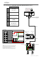
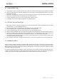
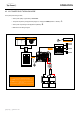
3.6.10 GROUNDING THE INVERTER - AC GROUNDING
The GP-IC-2000 should always be connected to a permanent, grounded wiring system. An Inverter / Charger system that is
properly grounded will reduce the risk of electric shock, reduce radio frequency noise. The main aim of any grounding system
istoprovideawelldened,verylowresistancepathfromtheelectricalsystemtothegroundingsystem.Thelowresistance
grounding path carries fault currents directly to ground if the electrical system malfunctions.
The neutral and safety ground should be connected at the AC source. The AC source could be shore power (utility power),
generator or the Inverter (battery bank). The AC neutral should be connected to one safety ground at a time, this single
connection is required to make the electrical panels neutral line safe by connecting it to ground. If more than one connection
between the neutral and ground is made, currents can circulate between neutral and ground and cause ground loop currents.
Ground loop currents can trip GFCIs and cause an electric shock hazard.
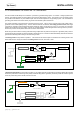
When using the GP-IC-2000 in Inverting mode and having multiple other AC power sources (shore or generator power), there is
the potential of having multiple connections between neutral and ground. The GP-IC-2000 automatically switches the neutral to
ground when switching from Inverting to AC Pass through mode.
In Inverting mode the relays switch to position 1. This means the AC neutral output is connected to the chassis ground on the
GP-IC-2000 which is usually connected to the Earth ground on the RV, work truck or boat.
In AC Pass through mode the relays switch to position 2. The chassis ground to neutral output on the GP-IC-2000 is disconnected
and the AC power source neutral to ground (usually located at utility panel or generator) is used to provide the neutral to ground
for the AC power being used in the RV, work truck or boat.
INSTALLATION