
User Manual

gpelectric.com | [page 33]
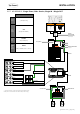
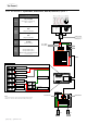
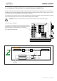
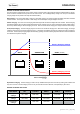
3.6.9 AC WIRING 4 - Split Phase, 50A Service, Dual IN, Dual OUT, Option 2
30A
IN 1
AC Hot 1 from main panel
ACN-IN
AC Neutral from main panel
AC Ground
AC Ground from main panel
OUT 1
AC Live to sub panel
ACN-OUT
AC Neutral to sub panel
AC Ground
AC Ground to sub panel
Shore Power
120 VAC
Generator Power
120 VAC
Main Panel
Sub Panel
AC Terminal Block
GP-IC-2000
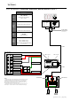
AC Power
Source
Maximum
Input
Breaker
required
Minimum
Wire
Size
Maximum
Inverter
Pass
Through
Capacity
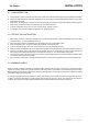
30A
(Single Pole Breaker)
#10 AWG
(Input & Output)
3600W
30A @ 120VAC
Single Phase - ≤30 Amp Service
120 VAC
≤30 Amps - 120VAC
Hot1 Only
#10 AWG
#10 AWG
GFCI
Outlet
GFCI
Outlet
Neutral Bus Bar
Ground Bus Bar
Neutral Bus Bar
Ground Bus Bar
CB2: 50A Breaker
Shore Power
120/240 VAC
Generator Power
120/240 VAC
IN 1
AC Hot 1
ACN-IN
AC Neutral
OUT 1
AC Live to sub panel
ACN-OUT
AC Neutral to sub panel
AC Terminal Block
IN 2
AC Hot 2
AC Power
Source
Maximum
Input
Breaker
Minimum
Wire
Size
Maximum
Inverter
Pass
Through
Capacity
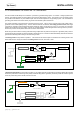
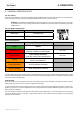
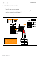
CB1: 50A
(located within the GP-IC-2000)
#6 AWG
(Input & Output)
12000W
50A @ 120VAC (Hot 1)
50A @ 120VAC (Hot 2)
Note: Loads must be correctly balanced between both
phases (Hot 1 and Hot 2) on the breaker panels in order to
get maximum capacity
Split Phase - ≤50 Amp Service
Install Option 2
#6 AWG
#6 AWG
AC Ground
AC Ground from main panel
AC Ground
AC Ground to sub panel
OUT 2
AC Live to sub panel
External
Transfer Switch
(only required if using
a hardwired generator
and shore power)
240 VAC
120 VAC
Sub Panel
GFCI
Outlet
GFCI
Outlet
Neutral Bus Bar
Ground Bus Bar
CB2: 50A
(located within the GP-IC-2000)
External
Transfer Switch
(only required if using
a hardwired generator
and shore power)
Hot 1 (Black)
CB1: 50A Breaker
120 / 240 VAC
50 Amps per 120 VAC leg.
Hot 1 + Hot 2.
120 VAC
120 VAC
GP-IC-2000
Maximum 30A Breaker
(single pole)
Notes:
* Using wiring option 2 for 50 Amp service will allow all AC devices to be
powered from the GP-IC-2000 in Inverting mode. Running devices that
use more than 2000W will cause the GP-IC-2000 to go into overload.
Operating high current draw loads (such as air conditioning units) could
severely deplete the battery bank power quickly.
* All previous converter / charger wiring must be disconnected f
rom the
breaker panel. The GP-IC-2000 is now used for battery bank charging
Notes:
* All previous converter / charger wiring must be disconnected from the
breaker panel. The GP-IC-2000 is now used for battery bank charging