
User Manual

[page 28] | gpelectric.com
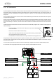
IN 1
AC Live from main panel
IN 2
AC Live from main panel
ACN-IN
AC Neutral from main panel
AC Inputs
AC Outputs
OUT 1
AC Live to sub panel
OUT 2
AC Live to sub panel
ACN-OUT
AC Neutral to sub panel
UNIT
ON/OFF
CHARGER
ON/OFF
SHORE POWER
UNIT READINGS
UNIT SETUP
REMOTE SETTINGS
Main Panel
Sub Panel
IN 1
AC Live from main panel
IN 2
AC Live from main panel
ACN-IN
AC Neutral from main panel
AC Inputs
AC Outputs
OUT 1
AC Live to sub panel
OUT 2
AC Live to sub panel
ACN-OUT
AC Neutral to sub panel
UNIT
ON/OFF
CHARGER
ON/OFF
SHORE POWER
UNIT READINGS
UNIT SETUP
REMOTE SETTINGS
Main Panel
Sub Panel
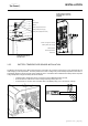
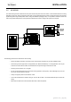
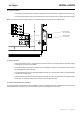
3.6.5 AC CONDUCTOR WIRING
Make sure the GP-IC-2000 is fully disconnected from the battery bank and no AC power is connected to the
Inverter / Charger before commencing any AC wiring connections
ACINPUTSWIRING(50ADualIN,DualOutConguration)
• Remove the AC cover plate.
• Route the wires: IN1 (Hot1), IN2 (Hot2), ACN-IN (neutral), and Ground from the main panel through the AC Input
strain relief clamp. Tighten the strain relief clamp securely on the wires. Always leave a little extra slack in the wiring.
• Connect the HOT1 wire (black) from the main panel to the Inverter / Chargers IN1 terminal. Connect the HOT2
wire (red) from the main panel to the Inverter / Chargers IN2 terminal. Tighten the terminals securely. Note: To
use the Battery Charger - IN1 must always be connected to an AC Input.
•
Connect the NEUTRAL (white) from the main panel to the Inverter / Chargers ACN-IN terminal. Tighten the
terminal securely.
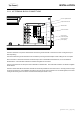
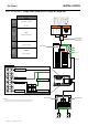
AC OUTPUTS WIRING
•
Route the wires (hot, neutral, and ground) from the sub panel through the AC INV. Output strain relief clamp.
Tighten the strain relief clamp securely on the wires. Always leave a little extra slack in the wiring.
•
Connect the OUT1 wire (black) and OUT2 (red) from the Inverter / Charger to the sub panel. Tighten the terminals
securely.
•
Connect the ACN-OUT Neutral out (white) from the Inverter / Charger to the sub panel. Tighten the terminal securely.
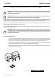
• To prevent possible damage to the case, always add additional external non-conductive strain relief when using
large diameter multi-conductor cables for AC inputs and AC outputs.
INSTALLATION