
User Manual

gpelectric.com | [page 25]
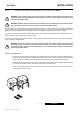
The following points must be observed for the AC Wiring
• Review the safety information at the start of this manual before completing any AC wire installation steps.
• All AC Wiring must be approved for the application (RV, Marine, Residential). For RV applications, this may be
solid wire in multi-conductor cables, but stranded wire is required if single conductors are used.
• All wiring must be rated to 75°C or higher.
• Do not connect the AC Output to an AC Power source (generator / shore power). Severe damage may occur and
will not be covered under the warranty.
• Always use properly rated circuit breakers / fuses.
• Color code and label all AC Cables coming to / from the GP-IC-2000. Use colored electrical tape or heat shrink
tubing.
• Make sure all cables have a smooth bend radius and no kinks are present.
INSTALLATION
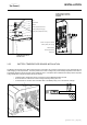
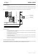
3.6 AC WIRING
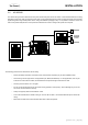
The cables linking the GP-IC-2000 to the main panel and the sub panel are the AC cables. These cables handle the incoming
alternating current (AC) utility or generator power which can be passed through the Inverter / Charger to directly power the main
appliances (pass through mode) and/or used to charge the batteries (charging mode). It is important to select the correct wire
size and to provide adequate over-current protection between the Inverter / Charger main panel and sub panel.
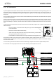
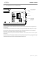
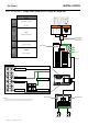
Main Panel
Sub Panel
120 VAC
120 VAC
240 VAC
ON
OFF
Battery Bank
Fuse or Circuit Breaker
GP-IC-2000
DC Panel
Earth Ground (RV, Boat Ground)
Equipment Grounding Bus Bar
Negative Bus Bar
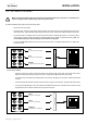
Battery Charging Voltage
BULK
ABSORPTION
FINAL (FLOAT)
Battery Charging Current
Time
Battery Disconnect Switch
(not required if circuit breaker is used)
ON
OFF
D
C
A
B
(Cabin)