
User Manual

gpelectric.com | [page 19]
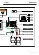
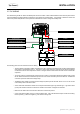
3.5 DC WIRING
The cables linking the GP-IC-2000 to the battery bank are the DC cables. These cables handle the Direct Current power used to
charge the batteries (Charging Mode) and power the main appliances (Inverter Mode). It is important to select the correct wire
size and to provide adequate over-current protection between the Inverter / Charger and battery bank.
INSTALLATION
The following points must be observed for the DC Wiring.
•
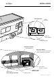
The DC positive and negative cables connected to the GP-IC-2000 from the battery bank should be linked together
with zip ties or electrical tape every 6”. This helps to reduce radio frequency interference and reduces the effects
ofinductancebothofwhichimprovetheInverter/ChargerwaveformandreducesthewearoftheInverterslter
capacitors.
• To ensure optimum Inverter/charger performance the number of connections between the battery bank and the
GP-IC-2000 unit should be minimized except from the over-current and battery disconnect devices. All additional
connection points will cause extra voltage drops.
• The Battery bank voltage must match the DC voltage required by the GP-IC-2000, which is 12V. Do not connect
a 24V battery bank to the GP-IC-2000.
•
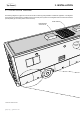
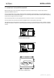
All DC cable wire terminations should use a crimped and sealed copper ring terminal lugs. Lugs with an 8mm
(5/16”) hole should be used to connect the DC cables to the Inverter / Chargers DC terminals.
• Make sure all cables have a smooth bend radius and no kinks are present.
• Colour code all DC Cables coming to / from the battery bank. Use coloured electrical tape or heat shrink tubing.
Red for positive (+), Black for negative (-) and Green for DC ground.
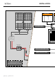
Main Panel
Sub Panel
120 VAC
120 VAC
240 VAC
ON
OFF
Battery Bank
Fuse or Circuit Breaker
GP-IC-2000
DC Panel
Earth Ground (RV, Boat Ground)
Equipment Grounding Bus Bar
Negative Bus Bar
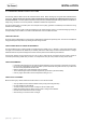
Battery Charging Voltage
BULK
ABSORPTION
FINAL (FLOAT)
Battery Charging Current
Time
Battery Disconnect Switch
(not required if circuit breaker is used)
ON
OFF
D
C
A
B