INVERTER/CHARGER IC 2000™ User Manual GP-IC-2000 © 2016 Go Power! By Carmanah Technologies Worldwide Technical Support and Product Information gpelectric.com ® Carmanah Technologies Corporate Headquarters 250 Bay St, Victoria, BC Canada V9A 3K5 Tel: 1.866.247.
Congratulations on purchasing your Go Power! GP-IC-2000 Inverter / Charger. The GP-IC-2000 Inverter / Charger combines the functions of a pure sine wave inverter, battery charger and AC transfer switch into one unit - saving space, installation time and system complexity. The GP-IC-2000 is designed for mobile and home power applications.
1. CONTENTS 2. GENERAL INFORMATION ������������������������������������������������������������������������������������������������������� 4 2.1 CAUTIONS ����������������������������������������������������������������������������������������������������������������������������������������������������4 2.2 DISCLAIMERS �����������������������������������������������������������������������������������������������������������������������������������������������7 2.
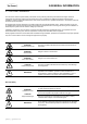
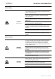
2.GENERAL INFORMATION 2.1 CAUTIONS / WARNINGS This document contains important safety instructions for the products produced by Carmanah Technologies. Read all instructions and cautionary markings on the product and on any accessories or additional equipment included in the installation. Failure to follow these instructions could result in severe shock or possible electrocution. Use extreme caution at all times to prevent accidents.
GENERAL INFORMATION Personal Safety Use safe lifting techniques when lifting this equipment as recommended by the Occupational Safety and Health Association (OSHA) or other local codes. Use standard safety equipment when working on this equipment, such as safety glasses, ear protection, steel-toed safety boots, safety hard hats, etc. Use standard safety practices when working with electrical equipment. (Remove all jewelry, use insulated tools, wear cotton clothing, etc.
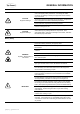
GENERAL INFORMATION When connecting cables from the inverter to the battery terminals, ensure the proper polarity is observed. Connecting the cables incorrectly can damage or destroy the equipment and the warranty may be annulled. CAUTION! Equipment Damage Thoroughly inspect the equipment prior to energizing. Verify that no tools or equipment have been inadvertently left behind. Ensure clearance requirements are strictly enforced.
GENERAL INFORMATION 2.2 DISCLAIMERS IMPORTANT: Please follow installation and wiring instructions exactly as outlined to ensure safety. We recommend installation by an RV technician or professional electrician to ensure adherence to relevant electrical codes.
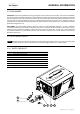
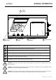
GENERAL INFORMATION 2.4 UNIT FEATURES 12 Dip Switches 11 Power ON/OFF Switch 10 Inverter/Charger Mode 9 Status LED ON/OFF INV. / CHR. MODE REMOTE AC Entry / Exit Terminals 1 DC Ground Terminal 2 POS NEG INV.
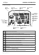
GENERAL INFORMATION 17 CB2 INPUT 50A 13 Exhaust Air Vents (Back side) 14 Built-in Handles CB1 INPUT 50A Serial Number Label 15 AC Input Circuit Breakers 16 AC Access Cover 12 Dip Switches - Reserved for future use. 13 Exhaust Air Vents - These cut-outs are used as ventilation openings. Air is drawn in through the front of the Inverter/ Charger and passes through to keep the electronics cool for optimum performance.
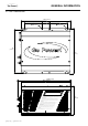
GENERAL INFORMATION 2.5 UNIT DIMENSIONS 13.6” (346mm) 2” (51mm) 4.9” (124mm) 4.9” (124mm) .28” (7mm) .51” (13mm) 12” (304mm) 12.6” (321mm) 14.9” (378mm) 13.7” (349mm) CAUTION: • TO PREVENT FIRE, DO NOT COVER OR OBSTRUCT VENTILATION OPENINGS. DO NOT MOUNT IN ZERO-CLEARANCE COMPARTMENT. OVERHEATING MAY RESULT. • RISK OF ELECTRIC SHOCK, DO NOT REMOVE COVER, NO USER SERVICEABLE PARTS INSIDE. REFER SERVICING TO QUALIFIED SERVICE PERSONNEL.
GENERAL INFORMATION 2.6 UNIT ACCESSORIES ® The IC 2000 Inverter/Charger has two accessories available: INVERTER ON/OFF SHORE POWER CHARGER ON/OFF REMOTE SETTINGS UNIT READINGS UNIT SETUP • IC 2000 series remote (not included). • Battery temperature sensor (BTS) (included). ENTER / SET BACK IC 2000 Remote This remote control device can be used for monitoring the performance of the unit. It is also used to program certain settings on the Inverter, Charger and AC pass through.
3. INSTALLATION 3.1 TYPICAL SYSTEM OVERVIEW The following diagrams on pages 12-15 show how the GP-IC-2000 is typically installed in a mobile RV application. The diagrams show where the Inverter/Charger is installed and how the mobile power system can be integrated with a Go Power! RV Solar Kit (sold separately by Go Power, please contact us direct.) Solar Panels Refrigerator Vent Cover Internal View TYPICAL RV INSTALLATION [page 12] | gpelectric.
INSTALLATION GP-IC-Remote Solar Controller ole ns Co RV ea Ar Cable to Battery Bank Cable to GP-IC-2000 Unit AC Power OUTPUT - to RV appliances AC Power INPUT - from Shore Power / Generator (Fuses / Breakers not shown) GP-IC-2000 Inverter / Charger Cables From Solar Charge Controller Cables to / from Battery Bank Battery Bank gpelectric.
INSTALLATION Shore Power 120/240 VAC Solar Panel Solar Panel AC Transfer Switch Refrigerator Vent Cover or Cable Entry Plate Main Pane Solar Charge Controller Earth Ground (RV, Boat Ground) Fuse Battery Temperature Sensor To Battery Bank To Battery Bank Typical RV Solar Kit (sold separately by Go Power) [page 14] | gpelectric.
el INSTALLATION Generator Power 120/240 VAC Remote Control (Optional) 120 VAC 240 VAC (cabin install) 120 VAC Sub Panel GP-IC-2000 DC Panel ON OFF Battery Disconnect Switch (not required if circuit breaker is used) Fuse or Circuit Breaker Battery Bank gpelectric.
INSTALLATION 3.2 LOCATION AND ENVIRONMENTAL REQUIREMENTS The GP-IC-2000 Inverter Charger must be installed in a location that meets the following requirements. 1. TEMPERATURE Make sure the GP-IC-2000 is installed in a location where the normal air temperature is between 0 °C and 50 °C. The cooler the better within this range. Note the GP-IC-2000 maximum output wattage will derate in temperatures above 45 °C. 2. MOISTURE Do not allow water or other fluids to come into contact with the GP-IC-2000.
MACHINE OU UNE ZONE CONTENANT UN ALLUMAGE — L’ÉQUIPEMENT PROTÉGÉ EST EXIGÉ Y BATTER P TEM INSTALLATION 3.3 MOUNTING THE INVERTER/CHARGER Before connecting any wires to the Inverter / Charger the unit must be mounted securely in a location which meets the requirements detailed in section 3.2. The GP-IC-2000 weighs: 39 lbs (17.6Kg). Take the necessary precautions required whilst lifting, moving and installing the unit. It is recommended to use two people whilst mounting the unit.
INSTALLATION 3.4 GENERAL WIRING SPECIFICATIONS The following sections detail how the GP-IC-2000 should be wired. Before starting any wiring read and understand these instructions. Wiring should meet all local codes and standards and be performed by qualified personnel such as a licensed electrician. The NEC (National electrical Code) and CEC (Canadian Electrical Code) provide the standards for safely wiring, wire sizes, over-current protection, installation methods and requirements.
INSTALLATION Main Panel 3.5 DC WIRING The cables linking the GP-IC-2000 to the battery bank are the DC cables. These cables handle the Direct Current power used to charge the batteries (Charging Mode) and power the main appliances (Inverter Mode). It is important to select the correct wire size and to provide adequate over-current protection between the Inverter / Charger and battery bank.
INSTALLATION 3.5.1 DC WIRE SIZING The distance between the battery bank and the GP-IC-2000 should be as short as possible to achieve maximum efficiency and to reduce fire hazards. The cables should be as short as possible and the overall length of both cables added together should be less than 10 ft (3m) to comply with code requirements. Keeping your wire runs as short as possible helps to prevent: low voltage shutdowns and nuisance tripping of the DC breaker because of increased current draw.
INSTALLATION DO NOT INSTALL ANYTHING BETWEEN RING LUG and DC TERMINAL Nut Split Washer Washer Battery Temperature Sensor Battery Cable (with ring lug) Battery Post (Negative Terminal) TE REMO Inverter / Charger DC Terminal Battery Cable (with ring lug) M8mm Washer M8mm Split Washer M8mm Nut DO NOT INSTALL ANYTHING BETWEEN RING LUG and BATTERY POST 3.5.
INSTALLATION 3.5.6 WIRING THE INVERTER/CHARGER TO THE BATTERY BANK WARNING: Lethal currents will be present if the positive and negative cables attached to the battery bank touch each other. During the installation and wiring process, ensure the cable ends are insulated or covered to prevent shorting the cables. WARNING: DO NOT connect the DC Wires from the battery bank to the GP-IC-2000 until all the DC and AC wiring is complete and the AC and DC overcurrent protection has been installed.
VDC 0 AH) 2 VDC 00 AH) VDC 0 AH) INSTALLATION 3.5.
INSTALLATION 3.5.8 DC GROUNDING To protect against electrical shock hazards the GP-IC-2000 metal chassis must be connected to the DC grounding system. The DC grounding system is sometimes referred to as the Earth ground or another designated ground. For example on an RV, the metal frame of the RV is designated as the negative DC ground / RV ground. On a boat, the ground is simply referred to as boat ground. The GP-IC-2000 consists of a DC and an AC section that are isolated through a transformer.
INSTALLATION 3.6 AC WIRING The cables linking the GP-IC-2000 to the main panel and the sub panel are the AC cables. These cables handle the incoming alternating current (AC) utility or generator power which can be passed through the Inverter / Charger to directly power the main appliances (pass through mode) and/or used to charge the batteries (charging mode).
INSTALLATION 3.6.1 AC POWER SOURCE TYPES AC Input power to the GP-IC-2000 can be supplied from a split-phase or dual-input single phase AC source. These sources typically include utility power or a generator. • Split Phase: This source has 4 lines: 2 hot lines, one neutral and one ground. The 2 hot lines are 120VAC and are 180 degrees out of phase with each other, so that the 2 voltages equal 240VAC.
INSTALLATION 3.6.4 AC TERMINAL BLOCK CONNECTIONS AC cover plate removed Phillips screw boss x3 IN1 IN2 ACN-IN OUT1 Terminal label IN1 IN2 ACN-IN AC terminal block OUT1 OUT2 OUT2 ACN-OUT ACN-OUT AC ground IN (from main panel) AC ground OUT size : 55x36.5mm (to sub panel) The GP-IC-2000 has a six-pole AC terminal block and two AC ground terminals to connect the Inverter / Chargers AC input and output wiring.
INSTALLATION 3.6.5 AC CONDUCTOR WIRING Make sure the GP-IC-2000 is fully disconnected from the battery bank and no AC power is connected to the Inverter / Charger before commencing any AC wiring connections AC INPUTS WIRING (50A Dual IN, Dual Out Configuration) • Remove the AC cover plate. • Route the wires: IN1 (Hot1), IN2 (Hot2), ACN-IN (neutral), and Ground from the main panel through the AC Input strain relief clamp. Tighten the strain relief clamp securely on the wires.
INSTALLATION AC GROUND WIRING • Connect the ground (Green) wire from the main panel to the AC Ground IN terminal. Tighten the terminal securely. • ConnectIN1 the ground (Green) wire from the sub panel to the AC Ground OUT terminal. Tighten the terminal securely. IN1 IN2 Note: The Ground terminals are lugs and they are not labelled within the compartment, see diagram below.
INSTALLATION 3.6.
INSTALLATION 3.6.
3.6.8 AC WIRING 3 - Split Phase, 50A Service, Dual IN, Dual OUT, Option 1 Split Phase - ≤50 Amp Service Install Option 1 120 / 240 VAC AC Power Source 50 Amps per 120 VAC leg. Hot 1 + Hot 2.
3.6.9 AC WIRING 4 - Split Phase, 50A Service, Dual IN, Dual OUT, Option 2 Split Phase - ≤50 Amp Service Install Option 2 120 / 240 VAC AC Power Source 50 Amps per 120 VAC leg. Hot 1 + Hot 2.
Minimum Wire Size #8 AWG & Output) Main Panel OUT 2 (Input AC Live to sub panel Hot 1 (Black) Maximum Inverter Pass Through Capacity al Bus Bar Neutral Bus Bar AC Ground AC Ground to sub panel ACN-OUT AC Neutral to sub panel INSTALLATION Ground Bus Bar 6000W Maximum 50A Breaker Sub Panel50A 50A @ 120VAC (Hot 1 + Hot 2) (single pole) 3.6.
Sub Panel Ground Bus Bar Notes: Neutral Bus Bar INSTALLATION * All previous converter / charger wiring must be disconnected from the breaker panel. The GP-IC-2000 is now used for battery bank charging Notes: * All previous breaker panel 3.6.11 DISABLING THE NEUTRAL TO CHASSIS GROUND CONNECTION The GP-IC-2000 has the automatic neutral to ground switching feature enabled as a factory default setting.
INSTALLATION 3.6.12 GROUNDING ON BOATS If you are installing the GP-IC-2000 on a boat there are some specific guidelines/standards to follow. The Inverter / Charger must be installed adhering to the standards of the AYBC (American Boat and Yacht Council). Some guidelines are outlined below but these notes do not replace the full guidelines detailed in the AYBC standard, always install the GP-IC-2000 using the AYBC standard as the primary reference.
INSTALLATION 3.7 FINAL INSPECTION 1. 2. 3. 4. 5. 6. Verify all cables / conduit runs are secured with zip ties or other non-conductive cable clamps to prevent damage from vibration. Ensure all cables that pass through walls, bulkheads or any other openings are protected against abrasion by using strain reliefs and/or grommets. Check all AC, DC and ground connections are securely tightened, and if required covered with suitable anti-seizing grease.
4. OPERATION 4.1 GENERAL OPERATING NOTES ON / OFF SWITCH When the GP-IC-2000 is first connected to the battery bank the ON/OFF switch must be lightly pressed to turn the Inverter ON. Once the Inverter has been turned ON, pressing the ON/OFF switch turns the Inverter on and off. WARNING: The ON/OFF switch does not turn the battery charger or remove AC pass through mode.
OPERATION BATTERY CHARGER SPECIFICATIONS The GP-IC-2000 is equipped with a PFC (Power Factor Corrected) and PI (Proportional Integral) multistage battery charger. These 2 features maximize the real power from AC Shore Power. The multistage battery charger can use up to four different charging stages to help monitor and keep the batteries healthy. Bulk Charging: This is the initial stage of charging. While bulk charging, the charger supplies the battery bank with controlled constant current.
OPERATION 4.2 AC POWER PASS THROUGH MODE In AC power pass through mode; • Shore power (utility or generator) is connected. • The power required by the appliances (fridge, TV, charger) is 3600W (30AAC x 120VAC) - 1. • Shore power is powering all the appliances (3600W) - 2. • Batteries are not being charged.
OPERATION 4.3 CHARGING MODE In charging mode; • Shore power (utility or generator) is connected and supplying 15AAC (1800W: 15AAC x 120VAC) - 1. • No power is required by the appliances (fridge, TV, charger). • Batteries are being charged up to 100 Amps DC per hour - 2.
3600W OPERATION 2 Main Panel 4.4 POWER SHARING MODE ON OFF In power sharing mode; • The power required by the appliances (fridge, TV, charger) is 4200W (35AAC x 120VAC) - 1. • Shore power (Utility or Generator) is connected and supplying 6000W (50AAC x 120VAC) - 2. • 4200W of AC power is passed through the Inverter / Charger to power the appliances - 3.
OPERATION Main Panel ON 4.5 GENERATOR MODE OFF 2 2000W In generator mode; • The power required by the appliances (fridge, TV, outlets) is 3600W (30AAC x 120VAC) - 1. • Battery Dis - Charging Shore power (utility or generator) is connected and supplying 2400W (20AAC x 120VAC) - 2.
OPERATION 4.6 INVERTING MODE In inverting mode; • The load power required by the appliances (fridge, TV, charger) is 2000W (16.7AAC x 120VAC) - 1. • The inverter supplies the 2000W (186 ADC x 12VDC x 0.9) of AC power required to power the appliances - 2. • Shore power (utility or generator) is not connected.
OPERATION 4.7 BATTERY TEMPERATURE SENSOR (BTS) OPERATION The GP-IC-2000 is delivered with a battery temperature sensor. By installing this sensor the charge voltages are automatically adapted for deviating temperature. With a BTS installed , if the temperature around the BTS is below 20°C the absorb and float charge voltage increases. If the temperature around the BTS is above 20°C, the absorb and float charge voltage decreases.
OPERATION 4.9 GP-IC-2000 FAULT CONDITIONS The GP-IC-2000 is protected against fault conditions and in normal use it will be rare to see any. If a fault condition does occur, the GP-IC-2000 will shut down as a safety measure to protect itself, the battery bank and the AC loads.
OPERATION Symptom No output power. Inverter LED is OFF Possible Cause Recommended Solution Inverter is switched OFF Turn the Inverter ON Battery voltage is too low. The battery voltage level has dropped below the Low Battery Cut Off (LBCO) Check all connections for a break in the circuit: Fuses, Circuit breakers, Cable terminals. The Batteries need charging. Battery voltage is too high.
5. SPECIFICATIONS Electrical Input Inverter Mode Specification Item GP-IC-2000 Nominal Voltage 12 VDC Absolute Max. DC Input 25 VDC HBCO / HBCI 17 VDC ±0.3V LBCO / LBCI 9.0 VDC ±0.3V Input Voltage Range 9 - 17 VDC ±0.3V Input Over-Voltage Protection 16.5 - 17 VDC Input Under-Voltage Protection 9 - 10.
6. WARRANTY RETURN PROCEDURE The Go Power! warranty is valid against defects in materials and workmanship for the specific product warranty period. It is not valid against defects resulting from, but not limited to: • • • • • Misuse and/or abuse, neglect or accident. Exceeding the unit’s design limits. Improper installation, including, but not limited to, improper environmental protection and improper hook-up. Acts of God, including lightning, floods, earthquakes, fire, and high winds.
7. END OF LIFE - RECYCLING INFORMATION Product E.O.L (End of life) Information This product required the extraction and use of natural resources. It may contain substances that could be harmful to the environment or human health if improperly handled at the product’s end of life.
END OF LIFE - RECYCLING INFORMATION 4. Remove the screws holding PCB #2. PCB #2 3 7 4 CFB PCB Recycling (small electronics) 5. Remove the screws holding the transformer. Transformer (Copper) 3 4 7 CFB Recycling (small electronics) Metals Copper 6. Remove the screws holding the fans. 7. Remove the screws holding PCB #3. 8. Fans The GP-IC-2000 has been fully dissambled Metal Base PCB #3 3 CFB Recycling 4 (small electronics) People. Planet. Profit.
© 2016 Go Power! By Carmanah Technologies Worldwide Technical Support and Product Information gpelectric.com ® Carmanah Technologies Corporate Headquarters 250 Bay St, Victoria, BC Canada V9A 3K5 Tel: 1.866.247.