
User's Manual

GO MBW Getting Started Guide
GO MBW Getting Started GuideGO MBW Getting Started Guide
GO MBW Getting Started Guide
Draft Version - Confidential - Page 25
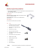
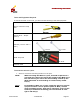
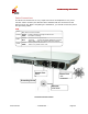
Power Cable Connection
Following is a diagram explaining how the power cable should be assembled prior to
connecting it to the WLS unit:
Power Cable Connection
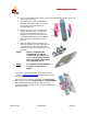
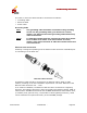
The power cable should be connected to a power supply unit. If there is already a -
48V power supply on site the WLS can be connected to it without the power supply
unit (PSU).
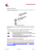
Depending on which cable you use, the following parameters should be applied:
• For 0.5mm 24awg with 2 tendon: each side can be up to 60m.
• For 1mm 18awg with 1 tendon: each side can be up to 120m.
Note: The power cable should be at least 14mm in diameter
(including insulation) and should be routed through a conduit
of at least 20mm diameter.
Noter: Le câble d’alimentation doit être d’au moins 14mm de
diamètre (isolation comprise), et doit être achemine a travers
un conduit d’au moins 20 mm de diamètre.
Power Up and Software Configuration
Configuration of the WNC unit is typically done once it is already installed. Because
the WLS unit is mounted on a roof or similar location, configuration of the unit is
typically done before mounting. Once the unit is mounted, it should be powered up
and connectivity confirmed. For details on configuring both the WNC and the WLS,
see the sections: Configuring the Wireless Network Controller and Configuring the
WLAN Sector Base Station.