
User's Manual


GO MBW Getting Started Guide
GO MBW Getting Started GuideGO MBW Getting Started Guide
GO MBW Getting Started Guide
Draft Version - Confidential - Page 18
2
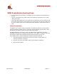
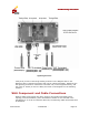
Verify that you have a shared grounding as shown in the diagram above.
In the above diagram:
1 Indicates the connection that is made between the WLS and the lightning
protector. In this case, an RJ45 connector (supplied with the unit) is used.
A CAT5 shielded cable stretches between the WLS unit and the lightning
protector.
2 Indicates the CAT5 shielded cable and its connection to the Router/Switch,
which is also accomplished with an RJ45 connector.
A Indicates shared grounding for the building.
B Indicates shared grounding for the cable.
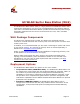
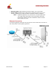
Power Connection
The following diagram illustrates how the WLS unit should be connected to the power
supply via a lightning protector.
Verify that you have shared grounding connected to both the lightning protector and
the WLS unit.
In the above diagram:
1 Indicates the two sides of the power cable connection between the WLS unit
and the lightning protector. The power connector is included in the WLS
package. Use a screwdriver to connect the power cables from both the