
User's Manual


GO MBW Getting Started Guide
GO MBW Getting Started GuideGO MBW Getting Started Guide
GO MBW Getting Started Guide
Draft Version - Confidential - Page 16
Power cord
Power cord
CAT 5 shielded
CAT 5 shielded
(Terminal Strip 4,7)
(Terminal Strip 4,7)
1
23 6
(Terminal Strip Data +,-/1,2)
(Terminal Strip Data +,-/3,6)
(Terminal Strip Data +,-/1,2)
(Terminal Strip Data +,-/3,6)
Power cord
Power cord
CAT 5 shielded
CAT 5 shielded
(Terminal Strip 4,7)
(Terminal Strip 4,7)
1
23 6
(Terminal Strip Data +,-/1,2)
(Terminal Strip Data +,-/3,6)
(Terminal Strip Data +,-/1,2)
(Terminal Strip Data +,-/3,6)
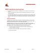
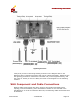
Lightning Protector
Verify that you have a shared grounding as shown in the diagram above. GO
Networks offers a lightning protector that can be ordered separately. Details of how
the lightning protector is connected to the WLS unit (on the Equipment Side), and
the router or switch (on the Line Side) are shown in the diagrams in the following
sections.
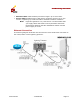
WLS Component and Cable Connections
Because cable requirements are often unique to the location and deployment
topology of each installation, power and Ethernet cables are not included in the
installation kit. In order to install the WLS unit, the following cables should therefore
be obtained: