
User's Manual


GO MBW Getting Started Guide
GO MBW Getting Started GuideGO MBW Getting Started Guide
GO MBW Getting Started Guide
Draft Version - Confidential - Page 11
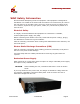
WNC Installation Instructions
• The unit should be mounted in a standard 19-inch equipment rack positioned on
a shelf.
• The two L brackets that are part of the unit should be connected to the 19-inch
rack with screws.
• The intake and exhaust ports for cooling air are located on the front and rear and
both sides of the chassis. Since there are no cooling ports on the top or bottom of
the unit, multiple units can be stacked with little clearance requirements within a
rack.
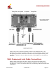
Cable Connections
In addition to the power supply connections, the WNC also features a control panel
on the front which enables you to connect the Access interface, Net interface, and a
Management interface (used during the initial configuration).
The MAC address on the sticker of the unit indicates the Access port. The High
Availability interface is not supported in Release 1 of the WNC. In addition, there are
two LEDs to indicate the Connection Status and Power Status of the unit.
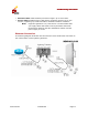
If the Status light is red, the following procedure should be followed:
1. Check the physical connections to the unit to make sure all cables are
securely and firmly connected.
2. Shut the unit down and restart. Wait 5 second before restarting.
3. Call technical support.