GO Metro Broadband Wireless Getting Started Technical Guide for WLP Wireless LAN Pico Base Station Version 2.
GO WLP Getting Started Guide Trademarks and Licensing Agreement © 2006 GO Networks, Inc. All rights reserved. All information contained in this document is protected by international copyright treaties. No information may be copied or reproduced without the express written consent of GO Networks Inc. GO Metro Broadband Wireless, Go MBW, WLAN Sector Base Station, WLS, GO WLAN Pico Base Station, WLP, GO Wireless Network Controller, and WNC are all trademarks of GO Networks Inc.
FCC Compliance Status The following information is for FCC compliance: This device complies with Part 15 of the FCC Rules. Operation is subject to the following conditions: 1. This device may not cause harmful interference, and 2. This device must accept any interference received, including interference that may cause undesired operation. This equipment has been tested and found to comply with the limits of a Class B digital device, pursuant to Part 15 of the FCC Rules.
Table of Contents Introduction ........................................................................................................................................3 Key Product Features ............................................................................................................................3 Organization ..............................................................................................................................................4 GO WLAN Pico Base Station (WLP).......
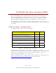
Introduction GO Networks’ WLP device is the key enabler for the Metro Broadband Wireless (MBW) Solution. Go Pico Cellular WiFi architecture offers a novel topology for metro WiFi networks which relies on the strengths of innovative XRF™ architectures. This architecture provides the coverage, capacity, and scalability required to deliver next-generation services and overcome the limitations of existing metro WiFi solutions.
Organization The GO Metro Broadband Getting Started Guide for the Wireless LAN Pico Base Station (WLP) offers information and instructions for quickly installing and configuring the WLP. The instructions and information are presented in one volume as follows: Introduction Contains introductory information about the WLP. GO WLAN Pico Base Station Presents a general description and overview of the WLP including content and safety procedures.
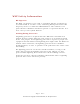
GO WLAN Pico Base Station (WLP) The GO WLAN Pico Base Station (WLP) complements the WLAN Sector Base Station (WLS) by delivering street-level coverage and providing capacity enhancements in dense metro areas over a single 802.11b/g channel, while backhauling traffic over multiple 802.11a/b/g radios. The WLP Base Station delivers omni-directional (360o) coverage while retaining full xRF smart antenna engine functionality for enhanced capacity and range.
WLP Safety Information RF Exposure The WLP, an outdoor access point, is compliant with the requirements set forth in CFR 47 section 1.1307, addressing RF Exposure from radio frequency devices as defined in OET Bulletin 65.
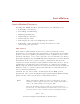
Installation Installation Process Installing the WLAN Pico Base Station involves the following steps: 1. Performing a Site Survey 2. Assembling and Mounting 3. Mounting the WLP unit 4. Connecting the Antennas 5. Connecting the cables 6. Powering up the unit and configuring the software 7. Performing a Post-installation Testing Procedure to verify connectivity and operation Site Survey Most wireless LANs include many access points installed in various locations in an overlapping radio-cell pattern.
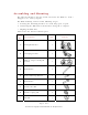
Assembling and Mounting The universal mount is used to attach and secure the WLP to a wall, a lamppost, or a variety of poles. The WLP mounting consists of the following stages: a. Securing the mounting brackets to a wall, lamp post, or pole. b. Connecting the WLP unit to the brackets using the ‘L’ adaptor. c. Aligning the WLP unit. Table 2 lists the universal mount parts: Item No.
Table 2: Mounting Kit Part List First connect the ‘L’ adaptor [C] to the WLP unit. As seen in Figure 1, the ‘L’ adapter is connected using an M8 [E] bolt, a washer spring [H], and a flat washer [G]. You must connect the ‘L’ adaptor on its normal-hole side and not on it grooved side. Figure 1: Mount ‘L’ Assembly After preparing the unit with the ‘L’ adaptor, install the brackets. Assembly of the mounting brackets in a lamppost or a pole installation differs according to the width of the pole.
Figure 2: Pole Bracket Assembly When mounting the WLP unit to a wall, use four 5 mm bolts to secure the bracket [A], using the holes seen in Figure 3. Wall-mounting bolts are not supplied with the unit. Wall mounting holes Figure 3: Bracket Wall Mounting After assembling the brackets, mount the WLP unit on to the bracket as seen in Figure 45. To accomplish this, use an M8 bolt [F] inserted to the grooved side of the ‘L’ adaptor, a flat washer [G], a spring washer [H] and a nut [I].
Once the WLP unit is mounted, release the bolts slightly and align the WLP unit horizontally, as seen in Figure 56. When the unit is perfectly aligned, firmly close all bolts, applying 120 lbs-inch of tilting torque. Figure 5: Aligning the WLP Mounting the Antenna Integral N-male connectors are used to mount the antennas on top of the WLP. The WLP holds four WiFi antennas for user access, operating on the 2.
3. Power Cable: The supplied AC power cable is deigned to connect directly to a lamppost power-tap feed. 4. RS-232 Console Cable: (The device might be pre-configured, so console connection isn’t required in the installation site.) To connect the WLP to a console (laptop computer) for configuration. - Page 12 of 31All contents are Copyright © 2006 GO Networks, Inc. All rights reserved.
Grounding Cable The grounding cable should be connected to the grounding screw at the bottom of the unit. Use a 1 mm / 18 awg grounding cable. Note: Connect the grounding cables before connecting any other cables. Do not remove the grounding cable when other cables are connected. Ethernet Connection Ethernet connection is used for wired backhaul connection or an interface to a third party wireless BH solution.
Power Up and Software Configuration The WLP unit is normally mounted on a high pole (or wall) where it is inconvenient to configure. However minimal connectivity must be verified so the unit can later be configured and monitored from the ground. In order to verify connectivity when installing the device, root devices must be installed and powered up first. The connectivity of the root device can be verified by the Ethernet ACT LED.
Configuring the WLP Following is a brief overview of the main CLI commands that are used to configure the WLP. A configuration example follows the detailed list of configuration commands. These and other CLI commands are detailed in the GO MBW CLI Reference Guide. Connect and Access the WLP Initial configuration of the WLP is done using a serial cable. A standard RS232-interface DB-9 cable is connected to the COM port of a laptop or a PC to the WLP unit’s console port.
Once the cable is connected, you can then operate a terminal program, such as HyperTerminal. The PC port should be configured as follows: d. Baud rate = 9600 e. Data bits = 8 f. Parity none g. Stop bits = 1 h. Flow control = None = To use HyperTerminal: From the Start menu: 1. Select All Programs > Accessories > Communications > HyperTerminal. 2. Define a new connection. 3. Right-click and select Properties. Set or verify the above values. 4. Click OK. Figure 8: HyperTerminal 5.
in turn, determines whether you can view configuration and operation parameters, or implement changes. A new user and password name should be added; however this default name and password can be used for the initial configuration. The default system name for the unit is set to WLS. Configuring the Management Connectivity Configuring the management connectivity involves setting the Fast Ethernet connection as well as defining the default gateway. These procedures are detailed in the following section.
By default, the channels are defined for use in a mixed mode. You can select a rate per channel for one of two states: g or mixed (a combination of g and b). The following CLI command syntax is used: configure interface dot11Radio 0 mode [g | mixed] Configuring Multiple SSIDs The SSID is a unique identifier that wireless networking devices use to establish and maintain wireless connectivity. Multiple access points on a network or sub-network can use the same SSID.
Enabling the Radio Interface By default, the WLP radio is disabled. You can, however, choose to enable it using the following CLI command syntax: configure interface Dot11Radio 0 [disable | enable ] Note: You can’t enable the wireless interface until at least one BSSID is attached to it. Configuring the WDS WDS protocol is used to support wireless backhauling and meshing of WLP and CPE units. WDS is supported over both the 2.4 GHz access radio and the 5 GHz backhaul radio.
Domain ROOT /FATHER HOP1/SON HOP1/SON/FATHER Hop2/son Figure 9: WDS Tree The WLP supports two modes of WDS operation: Manual and automatic topology detection. Manual Mode — Connection between two peers is done by manually entering each peer MAC address. Once the MAC address has been entered, the two peers are WDS-connected. Automatic Mode (AWDS) — Connection between two peers is done by automatically discovering the father and establishing the connection between the two peers.
WDS root configuration is controlled by: configure wds root [ true | false ] To display the current WDS configuration use: show wds params WDS is always used on the BH radio while the access radio can be configured to use as Access-only, pure backhauled, or mixed operation by the following command: configure interface dot11Radio 0 service [access | backhaul | both] To activate the automatic topology detection mode (meshing mode) the user has to enable this mode at both devices he wishes to connect and confi
To configure the WDS connection manually, use: configure wds add peer Note: Note: This command is used only for non-root WLP. Manual configuration can result in network loops. The WDS connection can be protected by configuring the WDS privacy. The user must configure all the units he wishes to connect with identical privacy settings.
Your WLP must be configured to support the Radius server communication. At a minimum, you must identify the Radius server software and define the method lists for Radius authentication. Alternatively, you can define method lists for Radius authorization and accounting. Identifying the Radius Server WLP-to-Radius server communication involves several components: a. IP address b. Authentication destination port c. Accounting destination port d.
e. WPA-Extensible-Authentication-Protocol (WPA-EAP): Using WPA-EAP key management, the client and the authentication server authenticate each other using an EAP authentication method, and the client and server generate a Pairwise Master Key (PMK). f. WPA-Pre-shared key (WPA-PSK): Using WPA, the server generates the PMK dynamically and passes it to the WLP. Using WPA-PSK, however, you configure a pre-shared key on both the client and the WLP, and that pre-shared key is used as the PMK.
Upgrading the WLP Software Periodically, new software upgrades are released in order to provide feature enhancements and maintenance. Following is one method you can use to update the software: g. Initiate the network download using a TFTP download server. Note: The WLP unit has two banks in the Flash memory (sw0, sw1). By default, the WLP will startup the software image from the sw1 bank.
To copy a new image into Flash memory (write to Flash memory): a. Use the import image from tftp command. b. The system is now ready to be reloaded. After reload, the system will operate with the new image. - Page 26 of 31All contents are Copyright © 2006 GO Networks, Inc. All rights reserved.
Appendix A: List of Acronyms Acronym Explanation 802.11 A family of specifications related to wireless networking, including: 802.11a, 802.11b, and 802.11g. AP Access Point. The hub of a wireless network. Wireless clients connect to the access point, and traffic between two clients must travel through the access point. Access points are often abbreviated to AP BSSID Broadcast Service Set Identifier DHCP Dynamic Host Configuration Protocol.
Acronym Explanation WPA-EAP WPA-Extensible Authentication Protocol WPA-PSK WPA-Pre-shared key - Page 28 of 31All contents are Copyright © 2006 GO Networks, Inc. All rights reserved.
Appendix B: Wiring Specifications Table 4: Console Port Signaling and Cabling with a DB-9 Adapter for the WLP Unit Console Port (DTE) RJ-45-to-RJ-45 Straight Cable RJ-45 to DB-9 Terminal Adapter Console Device Signal RJ-45 Pin RJ-45 Pin DB-9 Pin Signal No connection 1 1 8 CTS No connection 2 2 6 DSR No connection 3 3 5 GND GND 4 4 5 GND RxD 5 5 3 TxD TxD 6 6 2 RxD No connection 7 7 4 DTR No connection 8 8 7 RTS - Page 29 of 31All contents are Copyright © 200