
User Guide
The input source for the Model 2020 is selected on the lower Routing switch, located
near the lower left corner of the front panel. Only one source may be active through the
channel at a time; however, signals may be present at the other inputs since the source
select function does not ground unused inputs (see Specifications page of this manual for
separation figures). Phantom powering may remain On, if necessary, when switching
between input sources without damage to other input devices since the phantom supply
does not reach the Line or M/I inputs. It is, however, recommended that the phantom
power be turned Off when not in use to preserve power supply efficiency and eliminate
possible DC pops when changing input source selection.
An extremely wide range of gain settings (10dB of attenuation through 70dB of gain in
accurate 5dB steps) is available for all inputs of the Model 2020. This feature
accommodates a wide range of input signals, from extremely "hot" microphone inputs to
extremely "low" line or M/I inputs, which are commonly neglected by the vast majority of
peripheral audio processing devices. Indeed, the minimal 20dB of gain found in most
microphone preamplifiers can be excessive in certain circumstances, and decreases the
possibility of optimized gain staging. By the same token, real-world line level signals
often require more than the typical 10 dB of gain commonly accorded them. A high
quality rotary switch, marked Gain, is used to control the gain setting of the input
section, using a combination of discrete metal film resistors for the ultimate in accuracy,
stability, durability, and sonic integrity.
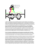
Incorporated into the input section, the Phase switch activates a relay just before the
balancing portion of the input section. No signal is present at the front panel Phase
switch--it is merely a relay control and LED indicator voltage. Engaging this switch
reverses the phase of the input signal, akin to swapping pins 2 and 3 on the Mic or Line
XLR's. In the case of an M/I input, the Phase function will change the absolute polarity
of a given input signal.
Integral to the operation of the input section is the balancing stage. This stage provides
common-mode rejection and precision balancing for the inputs, while also buffering the
input gain stage from all subsequent stages of the Model 2020. As with all sections of
the Discrete Input Channel, this stage exhibits extremely low noise and distortion, wide
bandwidth and dynamic range, and utilizes precise DC-servo coupling.
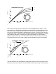
The Input Meter provides a valuable addition to the Model 2020 input section. This 5-
segment discrete LED display follows the input signal source and displays an accurate
indication of signal level after the input stage and high-pass filter. It should be noted
that the range and accuracy of this particular meter exceeds many common level
indicators. Indeed, with 54dB difference between the maximum indicator (+24dBu) and
the minimum indicator (-30dBu), the dynamic range of the meter presents quite a design
challenge; however, this meter is rugged and generally accurate to within +/-1dB of the
front panel legend. Fast transient response and a decaying LED fadeout help make this
meter extremely useful and pleasant to view.