
Manual


0020096324_01.1 - 09/10 - Glow-worm
- 5 -
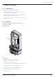
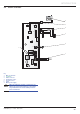
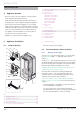
2.4 Electric schematic
X3
X2
X11
X12
X13
X1
P
NL
NLNL
54321
15 14 13 12 11
109876
20 19 18 17 16
X2
54321
15 14 13 12 11
109876
20 19 18 17 16
2
1
21
43
NL
7
1
2
4
5
6
3
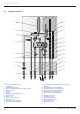
Key
1 Main circuit board
2 Systempro
3 E-bus connector
4 Temperature sensor
5 Pressure sensor
6 Pump
7 Mains power supply
e
When the hydraulic module is powered up, an
LED on the circuit board lights up. This LED is
only visible when the circuit board protective
cover is removed.
INTRODUCTION