
Manual


0020096324_01.1 - 09/10 - Glow-worm
- 12 -
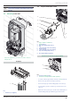
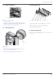
• Run the fi lling pump until the pipe (8) is completely purged.
• Close the air bleed on the heat pump.
• Close the valve (7) and pressurize the glycol water circuit to
between 1.5 and 2 bar using the pressure gauge (6).
• Close the valve (5) and stop the fi lling pump.
i
The glycol water level may reduce during the fi rst
month after commissioning the installation. It can
also vary according to the temperature of the heat
source.
Any residues of glycol water must be stored in an appropriate
container and used for the next refi ll.
• Give the container of glycol water residue to the user.
8 Electrical connections
e
Incorrect installation can cause electric shock or
appliance damage. The electrical connection of
the appliance must be made only by a qualifi ed
engineer.
i
Extra protection may be required at installation to
ensure voltage class II.
The external wiring must be earthed, with correct polarity and in
accordance with current standards.
i
Equipment compliant with CEI 61000-3-12.
Equipment compliant with CEI 61000-3-11.
The manufacturer declines any responsibility for damages to
persons or others caused by the incorrect installation of the
appliance earthing. This includes failure to comply with current
standards.
Component Voltage
(
cable section minimum)
Power cable 230 V (3 x 0.75 mm²)
E-bus cable 24 V (2 x 0.75 mm²)
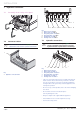
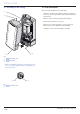
E-bus connection
1
Key
1 E-bus connector
9 Commissioning
• Refer to the system’s installation manual in order to
commission the installation
.
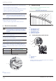
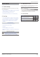
Pump fl ow / pressure curve
60
50
40
30
20
10
0
200 400 1000800
600 1200 1400
B
21 43
Key
1 Speed II by-pass closed
2 Speed II by-pass open
3 Speed I by-pass closed
4 Speed I by-pass open
A Available pressure (kPa)
B Flow in the circuit (l/h)
9.1 Setting the pump speed selector
1
2
3
Key
1 Speed selector
2 Speed I
3 Speed II
• Turn the selector (1) to select pump speed I or II according to
the fl ow/pressure curve above.
INSTALLATION