
Manual


0020096324_01.1 - 09/10 - Glow-worm
- 11 -
b
ATTENTION: The glycol safety valve may not be
connected to the drain. The heating safety valve
may be.
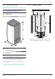
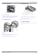
7.4 Mounting to the wall
• Attach the appliance to the wall in accordance with the
diagram above.
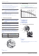
Insulation
1
Key
1 Insulation (not supplied)
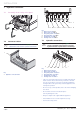
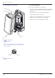
7.5 Glycol connection valves
1
2
3
4
5
6
8
7
Key
1 Glycol solution containert (*)
2 Filling pump (*)
3 Pipe on the fi lling pump outlet (*)
4 Cap
5 3-way valve with shut-off for refi lling
6 Pressure gauge
7 3-way valve with shut-off for refi lling
8 Pipe on the fi lling pump outlet (*)
(*) Not supplied with the appliance
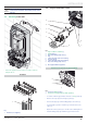
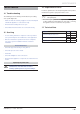
Position of the controls for glycol refi lling
1
2
Key
1 Controls in fi lling position
2 Controls in closed position (normal operation)
• In order to refi ll the glycol water circuit use a fi lling pump (2).
• Remove the caps (4) from the taps (5) and (7).
• Connect the pipe (3) from the fi lling pump to the valve (5).
• Insert the pipe (8) in the container (1) and connect it to the
valve (7).
• Open the valves (5) and (7) as shown on the drawing above.
• Start the fi lling pump (2) and fi ll the glycol water circuit.
INSTALLATION