
Manual


0020096324_01.1 - 09/10 - Glow-worm
- 10 -
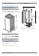
7 Hydraulic connection
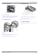
7.1 Assembly of the safety valve pipes
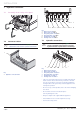
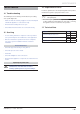
7.2 Connector sticker
i
A label located inside the cover displays the
identifi cation of the module’s hydraulic connections.
1
Key
1 Hydraulic connection label
1
23456
Key
1 Boiler fl ow circuit Ø ¾"
2 Boiler return circuit Ø ¾"
3 Heat pump return circuit Ø ¾"
4 Heat pump fl ow circuit Ø ¾"
5 Heating fl ow circuit Ø ¾"
6 Heating return circuit Ø ¾"
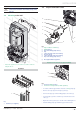
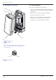
7.3 Hydraulic connections
b
ATTENTION: Before brazing the pipes ensure
that the (expanded) polypropylene around the
hydraulic module is protected to avoid damage.
6
3
1
2
4
5
Key
1 Boiler fl ow circuit Ø ¾"
2 Boiler return circuit Ø ¾"
3 Heat pump return circuit Ø ¾"
4 Heat pump fl ow circuit Ø ¾"
5 Heating fl ow circuit Ø ¾"
6 Heating return circuit Ø ¾"
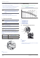
• Take care to clean the pipes before assembly removing any
debris or burrs. Grease and oils may need to be removed
they are not possible to remove by cleansing and fl ushing.
Foreign bodies in the system may enter the appliance and
interrupt its operation.
• Do not use any solvent products, due to the risk of damaging
the circuit.
• Do not braze connectors mounted in place :
this may damage the seals.
• Only use original seals supplied with the appliance.
• Check that there are no leaks. Repair if necessary.
• Connect the safety valves.
INSTALLATION