Installation and Servicing Hydraulic module BU
TABLE OF CONTENTS IN TR O DUCTI O N 1 Instructions guidance .........................................................................................................................2 1.1 1.2 1.3 1.4 2 Appliance description .........................................................................................................................3 2.1 2.2 2.3 2.4 3 Safety devices ...................................................................................................... 3 Data label ............
INTRODUCTION INTRODUCTION 1 Instructions guidance 1.1 Product documentation The instructions are an integral part of the appliance and must be handed to the user on completion of the installation. • Carefully read the manual, to understand all the information to enable safe installation, use and servicing. No liability can be accepted in the event of damage for not complying with the guidance in this instruction manual. 1.2 1.
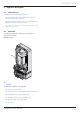
INTRODUCTION 2 2.1 Appliance description Safety devices 2 safety valves are installed on this appliance. - The heating safety valve opens when the pressure in the system exceeds 3 bar (3 x 10⁵ Pa). - The glycol safety valve opens when the pressure in the heat pump circuit exceeds 3 bar (3 x 10⁵ Pa). - The safety valves must be checked annually by your installer, at the time of servicing. 2.2 Data label The data label certifies the country where the appliance is intended to be installed.
INTRODUCTION - 2.
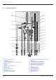
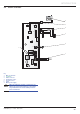
INTRODUCTION 2.4 Electric schematic 2 3 X3 1 4 3 2 1 X2 20 19 18 17 16 15 14 13 12 11 10 9 8 7 6 5 4 3 2 1 X2 20 19 18 17 16 15 14 13 12 11 10 9 8 7 6 5 4 3 2 1 4 2 5 X11 X13 N L X1 N L X12 P N L 1 N L 6 7 Key 1 Main circuit board 2 Systempro 3 E-bus connector 4 Temperature sensor 5 Pressure sensor 6 Pump 7 Mains power supply e When the hydraulic module is powered up, an LED on the circuit board lights up. This LED is only visible when the circuit board protective cover is removed.
INTRODUCTION 3 Safety instructions and regulations 3.2 Regulations IMPORTANT 3.1 e Safety instructions Incorrect installation can cause electric shock or appliance damage. • Never disable security devices and do not try to adjust them. • Be sure to consider the following handling techniques and precautions: - Grip the appliance at its base. - Use safety clothing where appropriate, e.g. gloves, safety footwear.
INSTALLATION Domestic Hot Water All domestic hot water circuits, connections, fittings must be in accordance with the relevant standards and water supply regulations. GB: Guidance G17 to G24 and recommendation R17 to R24 of the Water Regulations Guide. IE: The current edition of I.S.813 “Domestic Gas Installations”. Heating System In GB, it is necessary to comply with the Water Supply (Water Fittings) Regulations 1999 (for Scotland, the Water Byelaws 2000, Scotland).
INSTALLATION INSTALLATION 5 4 4.1 4.2 4.3 Appliance location 4.5 Elements supplied with the connector plate (*) Safety valve pipe Bag of seals Bag of connectors Heat pump return adaptor Heat pump outlet adaptor Heating return adaptor Heating outlet adaptor Boiler return adaptor Boiler outlet adaptor Bag of seals Seal ¾" Connector strip 5 5.1 5.2 5.3 5.4 5.
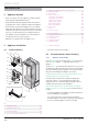
INSTALLATION 6.2.2 Heat pump circuit design 6.5.1 Mounting template Installation pipework must be designed and installed to ensure venting of air from the system is possible. b 6.3 Insulate the pipes with a UV- and hightemperature-resistant insulation. 50 min =320= Dimensions Hydraulic module 700 50 min 50 min =368= 890 57,5 57,5 40,5 57,5 57,5 17 • Drill the holes for the mounting screws using the drilling template supplied with the appliance connector plate. 418 i 6.
INSTALLATION 7 Hydraulic connection 7.1 Assembly of the safety valve pipes 1 6 5 4 3 2 Key 1 Boiler flow circuit Ø ¾" 2 Boiler return circuit Ø ¾" 3 Heat pump return circuit Ø ¾" 4 Heat pump flow circuit Ø ¾" 5 Heating flow circuit Ø ¾" Heating return circuit Ø ¾" 6 7.2 Connector sticker i A label located inside the cover displays the identification of the module’s hydraulic connections. 7.
INSTALLATION b 7.4 ATTENTION: The glycol safety valve may not be connected to the drain. The heating safety valve may be. 7.
INSTALLATION • Run the filling pump until the pipe (8) is completely purged. • Close the air bleed on the heat pump. • Close the valve (7) and pressurize the glycol water circuit to between 1.5 and 2 bar using the pressure gauge (6). 9 Commissioning • Refer to the system’s installation manual in order to commission the installation. Pump flow / pressure curve • Close the valve (5) and stop the filling pump.
INSTALLATION 9.2 Bypass adjustment 10 Draining the tank 1 6 Key 1 Bypass adjustment screw 5 4 3 2 1 • As necessary, turn this screw to adjust the pressure head available for the installation pressure drop. By default, the bypass is delivered in the closed position. • Isolate the installation by closing taps (6), (5), (2) and (1). 9.3 • Open the air bleed (chap.9.3) • Disconnect pipe (1) and connect to the drain tap.
INSTALLATION 12 Assembly of the casing 13 User information At the end of the installation, the installer must: 3 - explain the operation of the appliance and its safety devices to the user, if necessary provide a demonstration and answer any questions; 2 - hand over to the user all the required documentation, - fill in the documents where necessary; - advise the user of the precautions necessary to prevent damage to the system, appliance and the building; - remind the user to service the appliance annu
MAINTENANCE MAINTENANCE 16 Replacement of Parts In order to guarantee the safe and prolonged life of the product, manufacturers genuine spare parts must be used. 14 Trouble-shooting The following checks should be performed before proceeding onto specific diagnostics: - Make sure that the electricity supply has not been interrupted and that the appliance is connected correctly. i Use only the manufacturer’s authorised, original, new spare parts.
Subject to engineering changes 0020096324_01.1 - 09/10 GLOW-WORM Nottingham Road, Belper, Derbyshire. DE56 1JT www.glow-worm.co.uk Because of our constant endeavour for improvement, details may vary slightly from those shown in these instructions.