
Manual


0020096317_01 - 08/10 - Glow-worm
- 7 -
INTRODUCTION
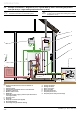
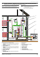
2.5 Example of Installation – Diagram 10 with Domestic Hot Water cylinder
i
Refer to the chapters “Hydraulic connection” and
“Electrical Connection” to connect the system.
b
This diagram shows the case of an installation with a
DHW cylinder.
EBUS
E
F
D
C
G
H
I
A
B
230V
3
5
4
2
1
6
8
7
9
10
11
1213
Key
1 Overheatingsafety(ifunderoorheating)
2 Hydraulic module
3 Domestic hot water cylinder
4 Systempro control unit
5 EBUS boiler
6 Wireless outdoor sensor
7 Non-return valve
8 DHW 2 port valve
9 Heat pump electrical supply + protection (This must have it's
own single isolation)
10 Boiler circuit 2 port valve
11 Heat pump
12 Heatpumpcircuitlter(notsupplied)
13 Glycol PRV discharge
A Heating circuit return
B Heatingcircuitow
C Boiler circuit return
D Boilercircuitow
E Heatpumpcircuitow
F Heat pump circuit return
G Heat pump circuit safety valve discharge