
Manual

0020096317_01 - 08/10 - Glow-worm
- 27 -
INSTALLATION
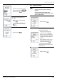
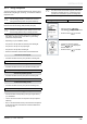
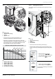
12.8.3 Heating circuit adjustment
2
3
1
4
Key
1 Speed control
2 Speed II (factory setting)
3 Speed I
4 By-pass screw
• Turn the control (1) to select pump speed I or I, in
accordance with the ow / pressure curve below.
• Depending on the design of the system the by-pass may
need further adjustment. It is adjusted clockwise to close and
anti-clockwise to open. This should be balanced to ensure
that it operates if the pump output is adjusted.
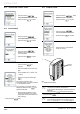
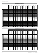
Hydraulic module pump ow / pressure curve
60
50
40
30
20
10
0
200 400 1000800
600 1200 1400
B
21 43
Key
1 Speed 2, bypass closed
2 Speed 2, bypass opened
3 Speed 1, bypass closed
4 Speed 1, bypass opened
A Available pressure (kPa)
B Flow within the circuit (l/h)
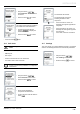
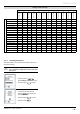
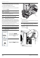
12.8.4 Venting the HP circuit
The venting of the HP circuit allows you to purge any air in the
HP circuit.
Ø14
A
B
1
3
4
1
2
Key
1 Air trap
2 Ø14mmatwrench(*)
3 Hose
4 Container(*)
(*) Notincluded
• Connect one end of the hose (3) to the trap (1).
• Insert the other end of the hose (3) into the container (4) in
order to recover any residual glycol during the venting of the
circuit.
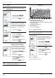
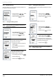
• Using the buttons ,
select Vent HP circuit on the screen.
• Press the button
to conrm.
• Conrm with the button in
order to begin the venting process.
You can start the heating circuit bleed at
the same time.