
Manual

0020096317_01 - 08/10 - Glow-worm
- 17 -
INSTALLATION
i
The level of glycol may decrease during the
rst month following the commissioning of the
installation. It may also vary in accordance with the
outdoor temperature.
Any residue of glycol solution should be kept in an appropriate
container to be re-used for the next lling.
• Ensure any leftover glycol solution is left with the end user
and retained in a safe place.
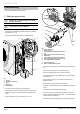
8 Filling the heating circuit
i
In the case of a multi-zone installation, ll the heating
circuit using the “Filling” mode when commissioning
the control box. “Filling” mode ensures lling by
automatically opening all of the circuit. Refer to the
chapter “Commissioning the Systempro control unit
► Commissioning ► Filling the heating circuit".
• For single zone installations (diagram 9.1), please refer to
your boiler installation manual for lling of the heating circuit.
• For mutiple zone installations (diagram 9.2, 9.3) please refer
to chapter "Commissioning ► Filling the heating circuit" for
instructions on conguring the systempro control box for
lling multiple zones.
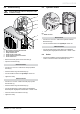
9 Activating the heat pump
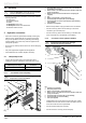
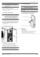
1
Key
1 ON/OFF button
• Switch ON the circuit breaker which is located on the
electrical panel and connected to the heat pump.
• Switch ON the heat pump button (1). Check that the green
LED located on the heat pump’s motherboard is on.
i
To locate the LEDs on the PCB, see the "Wiring
diagram" chapter in the heat pump instructions.
10 Activating the boiler
• Refer to the boiler instructions in order to adjust the boiler.
b
Ensure that the maximum heating temperature is
compatible with the installation.
b
Make sure the boiler pump is not in permanent
mode.
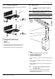
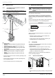
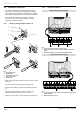
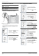
11 Activating the room thermostat
1
2
3
Key
1 Battery cover
2 Protective cover
3 Room thermostat
• Remove the protective cover (2) located in the battery
compartment following the order (A) to (C).
• The main screen of the room thermostat is displayed.