
Manual

0020096317_01 - 08/10 - Glow-worm
- 15 -
INSTALLATION
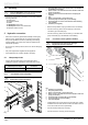
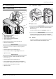
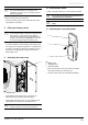
6.5.3 System connection
• Refer to the table below for the wiring of the systempro.
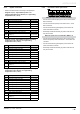
- Diagram 10 (10.1) : Hybrid Back-up with 1 low
heating temperature zone (30-40°C) or 1 high heating
temperature zone (< 80°C)
Key Description Cable min.
230V~ Control unit electrical supply 3 x 0.75 mm²
REL1 Hydraulic module 2 port valve 3 x 0.75 mm²
REL2 DHW cylinder 2 port valve (*) 3 x 0.75 mm²
IN1 DHW cylinder thermostat (*) 2 x 0.75 mm²
NTC2 DHW cylinder thermistor (*) 2 x 0.75 mm²
EBUS EBUS connection of the heat pump 2 x 0.75 mm²
EBUS
EBUS connection of the boiler (respect the
polarity +/-)
2 x 0.75 mm²
EBUS EBUS connection of the hydraulic module 2 x 0.75 mm²
- Diagram 10 (10.2) : Hybrid Back-up with 2 low heating
temperature zones (30-40°C) or 2 high heating
temperature zones (< 80°C)
Key Description Cable min.
230V~ Control unit electrical supply 3 x 0.75 mm²
REL1 Hydraulic module 2 port valve 3 x 0.75 mm²
REL2 DHW cylinder 2 port valve (*) 3 x 0.75 mm²
REL4 Heating circuit 2 port valve "area 2" 2 x 0.75 mm²
REL5 Heating circuit 2 port valve "area 1" 2 x 0.75 mm²
IN1 DHW cylinder thermostat (*) 2 x 0.75 mm²
IN3 DHW cylinder thermistor (*) 2 x 0.75 mm²
EBUS EBUS connection of the heat pump 2 x 0.75 mm²
EBUS
EBUS connection of the boiler (respect the
polarity +/-)
2 x 0.75 mm²
EBUS Connexion EBUS du module hydraulique 2 x 0.75 mm²
- Diagram 10 (10.2) : Hybrid Back-up with 3 low heating
temperature zones (30-40°C) or 3 high heating
temperature zones (< 80°C)
Key Description Cable min.
230V~ Control unit electrical supply 3 x 0.75 mm²
REL1 Hydraulic module 2 port valve 3 x 0.75 mm²
REL2 DHW cylinder 2 port valve (*) 3 x 0.75 mm²
REL3 Heating circuit 2 port valve "area 3" 2 x 0.75 mm²
REL4 Heating circuit 2 port valve "area 2" 2 x 0.75 mm²
REL5 Heating circuit 2 port valve "area 1" 2 x 0.75 mm²
IN1 DHW cylinder thermostat (*) 2 x 0.75 mm²
IN3 DHW cylinder thermistor (*) 2 x 0.75 mm²
EBUS EBUS connection of the heat pump 2 x 0.75 mm²
EBUS
EBUS connection of the boiler (respect the
polarity +/-)
2 x 0.75 mm²
EBUS Connexion EBUS du module hydraulique 2 x 0.75 mm²
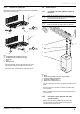
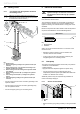
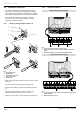
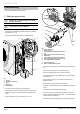
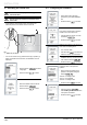
6.5.4 Connection of the 2 port valve
13
LN
230V~
13
LN
REL1
13
LN
REL2
13
LN
REL3
12
LN
REL4
12
LN
REL5
12
LN
IN1
When the 2 port valve is connected to REL3:
• Connect the neutral wire (blue) of the valve to the “N” of the
REL3 connector.
• Connect the live wire (brown) of the valve to the “L” of the
REL3 connector.
• Connect the earth wire (yellow/green) of the valve to the
earth of the REL3 connector.
• Electrically insulate the red and grey wires of the valve as
they are not used.
When the 2 port valve is connected to REL4 or 5:
• Connect the neutral wire (blue) of the valve to the “N” and
the live wire (brown) of the valve to the “L” of the REL4 or 5
connector.
• Connect the earth wire (yellow/green) of the valve to the
earth of the REL3 connector.
• Electrically insulate the red and grey wires of the valve as
they are not used.