
Manual

0020096317_01 - 08/10 - Glow-worm
- 13 -
INSTALLATION
6.2 Electrical wiring
e
Insert the Ebus 24V cable and 230V power cable
in different casings.
B
A
5
4
3
2
1
6
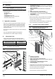
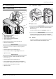
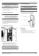
Key
1 230 V supply connection terminal block
2 Ebus connection terminal
3 Clamp for Ebus cable
4 Clamp for 230 V power cable
5 Access hatch to electrical connections
6 Access hatch screw
• Remove the screw (6) from the access hatch (5).
• Open the access hatch (5).
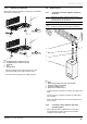
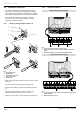
Ebus Connection
• Connect a 2 x 0.75 mm ² cable to the heat pump’s BUS
terminal (2).
• Pass the cable through the cable clamp (3).
• Connect the Ebus cable to the Systempro control unit.
• Tighten the clamp.
230V Connection
• Connect a 3 x 2.5 mm ² cable to the heat pump’s power
terminal 230V (1).
• Pass the cable through the cable clamp (4).
• Connect the heat pump’s power cable to the installation’s
electrical panel: single-phase network 230V + neutral + earth.
• Close the access hatch with the screw (6).
• Tighten the clamp.
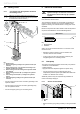
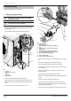
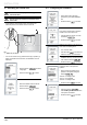
6.3 Hydraulic module
1
Key
1 EBUS connector
Ebus terminal
• Connect a 2 x 0.75 mm ² cable to the hydraulic module’s
BUS terminal (2).
• Connect the Ebus cable to the Systempro control unit.
230V Connection
• Connect the heat pump’s power cable to the installation’s
electrical panel: single-phase network 230V + neutral + earth.
6.4 Boiler
• Consult the installation manual supplied with the boiler in
order to connect the boiler to the electricity circuit.