
Manual

0020096317_01 - 08/10 - Glow-worm
- 11 -
INSTALLATION
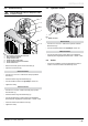
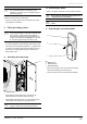
5.1.3 Removal of condensate
When the heat pump is operational, it will produce condensation
that needs to be drained off.
1
2
3
A
1
3
2
B
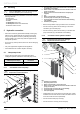
Key
A Congurationwithinclinationtotheleft
B Congurationwithinclinationtotheright
1 Heat pump
2 Plug
3 Drainage elbow
• Insert the drainage elbow (3) and pipe into the correct
opening depending on the angle of the heat pump.
• Seal off the other opening with the supplied plug (2).
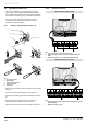
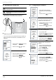
5.2 Boiler circuit
5.2.1 Connection from the hydraulic module to
the boiler
i
Make the connection limiting the load losses to a
minimum (the circuit should be as short as possible,
avoid bends and narrow sections...).
i
Refer to the installation manual delivered with the
boiler for domestic hot water system connections.
1
2
4
3
5
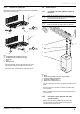
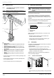
Key
1 Boiler
2 Return tubing leading to the boiler (not included))
3 Flow boiler tubing (not included)
4 Flow boiler connection (Ø ¾")
5 Return boiler connection (Ø ¾")
• Connect a pipe (2) to the return connection (5) leading to the
boiler.
• Connect a pipe (3) to the ow connection (4) leading away
from the boiler.
• Refer to the boiler instructions to connect the pipes (2) and
(3) to the boiler.
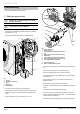
5.2.2 Connection of the domestic hot water
cylinder (option)
• Refer to the instructions supplied with the 2-way valve
and the domestic hot water cylinder for their hydraulic
connections to the boiler circuit.