
Manual

0020096317_01 - 08/10 - Glow-worm
- 10 -
INSTALLATION
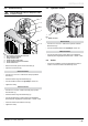
4.2 Mounting
i
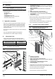
Install the Systempro control unit near the hydraulic
module to facilitate system commissioning.
• Consult the corresponding installation manual and install the
following elements:
- the heat pump,
- the hydraulic module,
- the boiler,
- the Systempro control unit,
- the Climapro2 wireless room thermostat,
- the wireless outdoor sensor.
5 Hydraulic connection
• Take care to clean the pipes before assembly removing any
debris or burrs. Grease and oils may need to be removed
they are not possible to remove by cleansing and ushing.
Foreign bodies in the system may enter the appliance and
interrupt its operation.
• Do not use any solvent products, due to the risk of damaging
the circuit.
• Only use original seals supplied with the appliance.
• Check that there are no leaks. Repair if necessary.
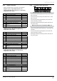
5.1 Heat pump circuit
• Comply with the values given in the table below when
making the hydraulic connections of the heat pump circuit.
Linear distance (without elbows or
additional pressure drops)
Min. diameter of tubes to
be installed
≤ 20 m Ø ¾"
≤ 30 m Ø 1"
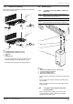
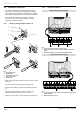
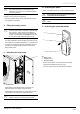
5.1.1 Connection to the heat pump
b
Insulate the pipes with an UV- and high-
temperature-resistant insulation.
1m min.
4
2
1
3
5 6
7
8
key
1 Heatpumpowcircuit¼turnshut-offvalveinthedirectionof
the building (not included)
2 Returncircuit¼turnshut-offvalveinthedirectionoftheheat
pump (not included)
3 Return circuit hose in the direction of the heat pump (not
supplied)
4 Cap
5 Return connection (Ø1 ") to the heat pump
6 Flow heat pump connection (Ø1 ") to the building
7 Flow heat pump circuit hose in the direction of the building
(not supplied))
8 Insulation (not supplied)
• Remove the protection caps (4) located on the connections.
• Connect a hose (3) and a shut-off valve (2) to the return
connection (5) to the heat pump.
• Connect a hose (7) and a shut-off valve (1) to the ow heat
pump connection (6) in the direction of the building.
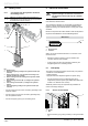
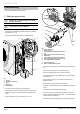
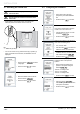
5.1.2 Connection to the hydraulic module
b
Insulate the pipes with an UV- and high-
temperature-resistant insulation.
7
5
6
1
2
3
4
Key
1 Insulation (not supplied)
2 Heat pump return circuit
3 Return connection (Ø1 ") to the heat pump
4 Returncircuit¼turnshut-offvalveinthedirectionoftheheat
pump (not included)
5 Flow heat pump connection (Ø1 ") to the building
6 Flow heat pump circuit to the building
7 Filter (not supplied)
• Install a lter to the circuit returning to the heat pump. Install
it between the 2 shut-off valves in order to be able to remove
it from the circuit and clean it periodically.
• Connect the ow heat pump circuit (6).
• Connect the return circuit (2) to the heat pump.