System Installation Hybrid Back-up
Table of contents INTR O D U C T IO N 1 Instructions guidance..........................................................................................................................3 1.1 1.2 1.3 1.4 2 System description..............................................................................................................................3 2.1 2.2 2.3 2.4 2.5 3 Product documentation........................................................................................... 3 Associated documents.
Table of contents Co mm issioning 7 Filling the glycol circuit......................................................................................................................16 8 Filling the heating circuit...................................................................................................................17 9 Activating the heat pump..................................................................................................................17 10 Activating the boiler........
INTRODUCTION INTRODUCTION 1 Instructions guidance 1.1 Product documentation The instructions are an integral part of the system appliances and must be handed to the user on completion of the installation in order to comply with the current regulation. • Carefully read the manual, to understand all the information to enable safe installation, use and servicing. No liability can be accepted in the event of damage for not complying with the guidance in this instruction manual.
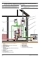
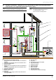
INTRODUCTION 2.2 i Example of Installation – Diagram 10 (10.1) : Hybrid Back-up with 1 low heating temperature zone (30-40°C) or 1 high heating temperature zone (< 80°C) Refer to the chapters “Hydraulic connection” and “Electrical Connection” to connect the system. b This diagram shows the case of an installation with a single zone low temperature heating floor (= outlet temperature < 40°C).
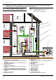
INTRODUCTION 2.3 i Example of Installation – Diagram 10 (10.2) : Hybrid Back-up with 2 low heating temperature zones (30-40°C) or 2 high heating temperature zones (< 80°C) Refer to the chapters “Hydraulic connection” and “Electrical Connection” to connect the system. b This diagram shows the case of an installation with a dual zone low temperature heating floor (= outlet temperature < 40°C). Zones must be same temperatures.
INTRODUCTION 2.4 i Example of Installation – Diagram 10 (10.3) : Hybrid Back-up with 3 low heating temperature zones (30-40°C) or 3 high heating temperature zones (< 80°C) Refer to the chapters “Hydraulic connection” and “Electrical Connection” to connect the system. b This diagram shows the case of an installation with a dual zone low temperature heating floor (= outlet temperature < 40°C). Zones must be same temperatures.
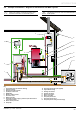
INTRODUCTION 2.5 i Example of Installation – Diagram 10 with Domestic Hot Water cylinder Refer to the chapters “Hydraulic connection” and “Electrical Connection” to connect the system. b This diagram shows the case of an installation with a DHW cylinder.
INTRODUCTION 3 Safety instructions and regulations 3.1 e Safety instructions Incorrect installation can cause electric shock or appliance damage. • Never disable security devices and do not try to adjust them. • Be sure to consider the following handling techniques and precautions: -- Grip the appliance at its base -- Use safety clothing where appropriate, e.g. gloves, safety footwear. R410A Refrigerant Fluid b • Use only R410A refrigerant.
INSTALLATION INSTALLATION 4 System appliance installation 4.1 4.1.1 Recommendations before installing Heating circuit design General The heat transmitters may be low temperature (eg underfloor heating or high temperature (radiator...). The pipe sections are to be determined using a flow / pressure curve (refer to the chapter "Activating the control unit" ► Commissioning ► Heating circuit adjustment").
INSTALLATION 4.2 Mounting i 1 Install the Systempro control unit near the hydraulic module to facilitate system commissioning. • Consult the corresponding installation manual and install the following elements: - the heat pump, - the hydraulic module, - the boiler, - the Systempro control unit, - the Climapro2 wireless room thermostat, - the wireless outdoor sensor. 5 Hydraulic connection • Take care to clean the pipes before assembly removing any debris or burrs.
INSTALLATION 5.1.3 5.2 Removal of condensate When the heat pump is operational, it will produce condensation that needs to be drained off. 1 A 5.2.1 Boiler circuit Connection from the hydraulic module to the boiler i Make the connection limiting the load losses to a minimum (the circuit should be as short as possible, avoid bends and narrow sections...). i Refer to the installation manual delivered with the boiler for domestic hot water system connections.
INSTALLATION 5.3 5.3.1 i 6 Heating circuit Connection from the hydraulic module to the heating circuit Make the connection limiting the load losses to a minimum (the circuit should be as short as possible, avoid bends and narrow sections...). 5 Electrical connections e Incorrect installation can cause electric shock or appliance damage. The electrical connection of the appliance must be made only by a qualified engineer.
INSTALLATION 6.2 e Electrical wiring 6.3 Hydraulic module Insert the Ebus 24V cable and 230V power cable in different casings. 1 2 3 4 1 5 Key 1 EBUS connector Ebus terminal 6 B • Connect a 2 x 0.75 mm ² cable to the hydraulic module’s BUS terminal (2). • Connect the Ebus cable to the Systempro control unit.
INSTALLATION 6.5 Systempro control unit 6.5.2 Internal connection 230V connection (High voltage) • The electrical installation in the dwelling must permit the power supply to the equipment to be isolated by a double pole isolation switch and be fused. The double pole isolation switch must incorporate a gap of 3mm between the contacts. • Use a power cable suitable for the mains connection, minimum 0.75 mm. If the cable is damaged, it must be replaced by a qualified engineer. 6.5.
INSTALLATION 3 x 0.75 mm² IN1 DHW cylinder thermostat (*) 2 x 0.75 mm² NTC2 DHW cylinder thermistor (*) 2 x 0.75 mm² EBUS EBUS connection of the heat pump EBUS connection of the boiler (respect the polarity +/-) 2 x 0.75 mm² EBUS connection of the hydraulic module 2 x 0.75 mm² EBUS 2 x 0.75 mm² -- Diagram 10 (10.2) : Hybrid Back-up with 2 low heating temperature zones (30-40°C) or 2 high heating temperature zones (< 80°C) Key Description 230V~ Control unit electrical supply 3 x 0.
INSTALLATION Commissioning • Open all the hydraulic circuits’ valves. 7 B Filling the glycol circuit A b Warning! Do not dispose of glycol into drains and the environment. b We recommend that you use propylene glycol enriched with corrosive inhibitors. 4 • Mix 1 part propylene glycol with 2 parts water. This mixture ensures antifreeze protection down to an exterior temperature of -15 °C. 3 5 2 • Use an antifreeze test kit to ensure accurate dosing.
INSTALLATION i 10 Activating the boiler The level of glycol may decrease during the first month following the commissioning of the installation. It may also vary in accordance with the outdoor temperature. • Refer to the boiler instructions in order to adjust the boiler. Any residue of glycol solution should be kept in an appropriate container to be re-used for the next filling. • Ensure any leftover glycol solution is left with the end user and retained in a safe place.
INSTALLATION 12 Activating the control unit 12.1 a Ensure that the heat pump and heating circuits have been filled. e Ensure that all the electrical connections have been made. • Switch ON the circuit breaker which is located on the electrical panel and connected to the control unit. Configuring the installation • Follow and confirm the steps prompted by the initial installation aid. • Press the button to confirm. Your system corresponds to diagram number "10" in the control unit.
INSTALLATION 12.2 • Select the corresponding cylinder type using the buttons . to confirm. • Press the button e Wiring summary To check or modify a connection: • Set the control box switch to the Off (O) position. • Set the circuit breaker located on the electrical panel and connected to the control box to the Off position. The control unit summarizes your installation. • If this is correct, confirm with the . button • Press the button .
INSTALLATION 12.3 "Thermostat / sensor" menu 12.5 Outdoor sensor • Using the buttons , select Rmstat/sensor on the screen. • Press the button 12.4 • Using the buttons , select Outdoor sensor on the screen. to confirm. • Press the button to confirm. Thermostat(s) • Using the buttons , select Connection on the screen. • Press the button • Using the buttons , select Roomstat(s) on the screen. • Press the button to confirm. to confirm. • Press the button on the outdoor sensor to connect.
INSTALLATION • Using the buttons , select External T ºC correction on the screen. • Press the button The automatic test will start. to confirm. The results appear in seconds, indicating the status of each component. This setting is automatically modified in the installer room thermostat menu. -- If the connection is not correct, the message "Not OK" appears opposite the component. In this case, check the connections. • Increase or decrease with the to display the buttons desired correction.
INSTALLATION 12.7.1 b Heating Heating curve The maximum heating output temperature must be adjusted in accordance with the characteristics of your installation. A 1 2 3 • Using the buttons , select Heating on the screen. This menu allows you to adjust the installation’s maximum heating output temperature (value adjustable between 30 ° C and 80 ° C - factory setting: 73°C). • Press the button • Press the button B to confirm.
INSTALLATION 12.7.4 Energy management The energy efficiency coefficient determines the switching point between two energies (gas, electricity), in accordance with their respective costs. i The systempro makes a selection in accordance with the energy efficiency coefficient.An incorrect setting will adversely affect the system efficiency. i If the values you noted down do not correspond to the values shown in the tables opposite, this means that there is probably an error.
INSTALLATION NATURAL GAS with electricity price excluding VAT (GBP) of natural gas in kWh * 0,191 to 0,200 0,181 to 0,190 0,171 to 0,180 0,161 to 0,170 0,151 to 0,160 0,141 to 0,150 0,131 to 0,140 0,121 to 0,130 4,0 4,5* 5,0* 5,4* 5,9* 6,4* 6,8* 7,3* 7,8* 8,3* 8,7* 9,2* 3,6 4,0 4,4* 4,9* 5,3* 5,7* 6,1* 6,5* 7,0* 7,4* 7,8* 8,2* 0,111 to 0,120 0,091 to 0,100 0,0200 to 0,0225 0,0226 to 0,0250 0,101 to 0,110 0,080 to 0,090 Price (GBP) of electricity per kWh excluding VAT
INSTALLATION Heating oil with electricity price excluding VAT (GBP) of heating oil per litre 0,191 to 0,200 0,181 to 0,190 0,171 to 0,180 0,161 to 0,170 0,151 to 0,160 0,141 to 0,150 0,131 to 0,140 0,121 to 0,130 0,111 to 0,120 0,101 to 0,110 0,091 to 0,100 0,080 to 0,090 Price (GBP) of electricity per kWh excluding VAT 0,400 to 0,425 2,1 2,3 2,6 2,8 3,0 3,3 3,5 3,8 4,0 4,3 4,5 4,7 0,426 to 0,450 1,9 2,2 2,4 2,6 2,9 3,1 3,3 3,6 3,8 4,0 4,2 4,5 0,451 to 0,475 1,8 2,
INSTALLATION 12.8 Commissioning 12.8.2 Venting of the heating circuit enables the purging of any air in the heating circuit. This menu allows you to carry out the necessary operations on the appliances following installation. • Using the buttons , select Air venting on the screen. • Using the buttons , select Commissioning on the screen. • Press the button 12.8.1 i Venting the heating circuit to confirm. • Press the button to confirm. • Open the different heating circuit air vent.
INSTALLATION 12.8.3 Heating circuit adjustment 12.8.4 Venting the HP circuit The venting of the HP circuit allows you to purge any air in the HP circuit. 3 1 2 2 B Ø14 1 A 3 4 Key 1 Speed control 2 Speed II (factory setting) 3 Speed I 4 By-pass screw 4 1 • Turn the control (1) to select pump speed I or I, in accordance with the flow / pressure curve below. • Depending on the design of the system the by-pass may need further adjustment.
INSTALLATION • Using a flat wrench (2), open the trap (1) a ¼ turn in order to remove the air present in the glycol circuit, then close it quickly (in order to avoid emptying the circuit). The venting process is carried out for 15 minutes. • Repeat this last operation at the end of the venting procedure. • Press the button . b The venting may result in a drop in the glycol circuit pressure. b When venting is complete, make sure that the various heating circuit air vent are open.
INSTALLATION 12.9.1 "Heat pump" flow / pressure curve 1 Information on the boiler 2 60 • Using the buttons select Boiler on the screen. 50 40 • Press the button 30 , to confirm. 20 10 0 300 600 900 1200 This screen indicates whether the boiler responds to a request (ON or OFF). B • Press the button fault report. Key 1 With water 20°C 2 With glycol solution (mix at 30%) at 20°C A Available pressure (kPa) B Flow within the circuit (l/h) 12.
INSTALLATION 12.9.3 System information 12.9.5 • Using the buttons , select System on the screen. • Press the button i Information about the domestic hot water cylinder option This menu is only available if you have chosen the domestic hot water tank option. to confirm. • Using the buttons , select DHW cylinder on the screen. This screen indicates: - the external temperature, - the heating circuit pressure.
INSTALLATION 12.11 Heating system test 12.12.3 • Ensure that there is a heating demand to the control unit. In the case of a multi-zone configuration, perform the test zone by zone and ensure that the appropriate zone gets warmer. Description of the main screen This screen indicates: - the overall system efficiency, - the current date, - the time. • Ensure that all the heating circuit’s thermostatic valves are open. • Balance the heat emitters, if necessary. 12.12 Finishing 12.12.
INSTALLATION 13 Re-check and restart • Once the system is installed, check the operation of each appliance. • Start the system to ensure that any adjustments operate correctly and check that the appliances operate safely. • Reset the fault reports for all appliances. To do this, see chapter "Activation > Components Info”. • Check the water-tightness of the appliances and eliminate any leaks. • Check the entire control and safety system, settings and operation.
MAINTENANCE MAINTENANCE 15 Trouble-shooting 15.1 Fault diagnosis The following checks should be performed before proceeding onto specific diagnostics: -- Make sure that the electricity supply has not been interrupted and that the appliance is connected correctly. -- Ensure that the isolating valves are open. -- Check that all external controls are connected correctly. 15.2 i 15.2.
MAINTENANCE Fault codes Description 030 Failure in communication with the zone 1 wireless room thermostat. 031 Failure in communication with the zone 2 wireless room thermostat. 032 Failure in communication with the zone 3 wireless room thermostat. 033 Failure in communication with the zone 4 wireless room thermostat. 034 Failure in communication with the zone 5 wireless room thermostat. 035 Failure in communication with the zone 6 wireless room thermostat.
MAINTENANCE 16 Servicing 16.1 Heat pump test Annual Maintenance • Consult each of the system component’s instructions for more information about the corresponding maintenance operations. 16.2 The maintenance menu includes the installation menu function, plus 2 additional functions. for 7 • Enter the installer maintenance access code (35). to confirm. • Press the button 16.2.1 to confirm. • Press the button Control unit maintenance menu • Press the button seconds.
MAINTENANCE 16.2.2 Heating zones test i The heating zones can only be tested if you have installed multiple zone valves. • Using the buttons , select Zones on the screen. • Press the button • Select the zone you want to test . using the buttons to activate • To disable the test, press the button . • Press the button to confirm. DHW cylinder test i This menu provides access to Aftersales Service information. • Using the buttons , select Parameters on the screen. • Press the button to confirm.
Subject to engineering changes 0020096317_01 - 08/10 Glow-worm Nottingham Road, Belper, Derbyshire. DE56 1JT www.glow-worm.co.uk Because of our constant endeavour for improvement, details may vary slightly from those shown in these instructions.