
Manual

16
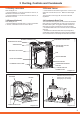
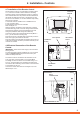
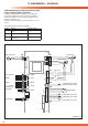
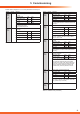
4 Installation - Controls
Temperature sensor EAO
(Frost protection sensor)
ϑ
Temperature sensor SAI
ϑ
Temperature sensor SAO
ϑ
Temperature sensor EAI
Bypass Motor
ϑ
X 1X 9
X 11
X 10
X 13
X 14
X 12
X 15
X 16
F4
2AT
X 3
X 4
X 2
X 5
X 6
X 17
X 7
X 8
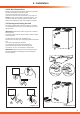
Switch 1
Alarm input
Alarm output
Switch 2
BUS connection
0 - 10 V Control
signal (analog)
Mains connection
M
Control signal
Control signal
+
-
Analog
PC
connection
Error In Err. Out
D OH
Switch 2
0 - 10 V
Hz
Gnd
0 - 10 V
Hz
Gnd
Bus
N L
230 V~
N L N L
Switch 1
white whitewhite
red blue white
white
white white white
- + 1 2 1 2D OH
Freh air fan
Exhaust air fan
1
6
2
7
3
8
4
5
9
10
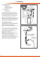
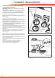
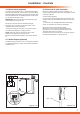
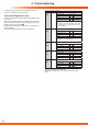
4.9 Establishment of Electrical Connection
of the 3-stage Switch (optional)
In addition to the standard control unit, you can also use
a universal 3-stage switch, routed into X12 of the PCB, to
control the ventilation unit. This must be potential-free (no
voltage), see diagram 4.9.
Connect as shown in diagram 4.10 to the clamps „0↓”, “D↑”
and “H↑”.
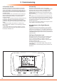
The following switch positions are possible:
Position Function Electrical contact
1 ("0")
Control system with remote
control
0
↓
open
2 ("D") Day position (fans stage 2) 0↓ connected to D↑
3 ("H")
HIGH position
(fans stage 3)
0↓ connected to H↑
Diagram 4.9