
Manual


0020096321_00 - 07/10 - Glow-worm
- 7 -
INTRODUCTION
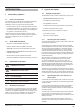
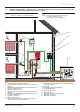
2.5 Example of Installation – Diagram 4 : Standalone with Domestic Hot Water cylinder
A Heating circuit return
B Heating circuit fl ow
C Domestic hot water fl ow
D Cold water supply
E Heat pump circuit return
F Heat pump circuit fl ow to cylinder circuit
G Heat pump circuit fl ow to module circuit
H Heat pump circuit return
Key
1 Overheating safety (if underfl oor heating)
2 "Electrical" hydraulic module
3 Systempro control unit
4 Power relay for the electric heater (not supplied)
5 Exchanger tank electric top-up heater
6 Domestic hot water tank
7 "Electrical" hydraulic module electrical supply + protection
(This must have it's own single isolation)
8 Heat pump electrical supply + protection (This must have it's
own single isolation)
9 Heat pump
10 Heat pump circuit fi lter (not supplied)
11 3 port valve
12 Glycol PRV discharge
i
Refer to the chapters “Hydraulic connection” and
“Electrical Connection” to connect the system.
EBUS
230V230V
H
G
E
F
C
D
A
B
1
2
3 4
8
10
5
1112
7
8
6
9