
Manual


0020096321_00 - 07/10 - Glow-worm
- 6 -
INTRODUCTION
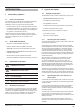
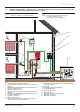
2.4 Example of Installation – Diagram 4 (4.3) : Standalone + with 3 low heating temperature zones
(30-40°C) or 3 middle heating temperature zones (< 60°C)
i
Refer to the chapters “Hydraulic connection” and
“Electrical Connection” to connect the system.
b
This diagram shows the case of an installation with a
three zone low temperature heating fl oor
(= outlet temperature < 40°C).
Zones must be same temperatures.
230V
EBUS
D
E
C
B
A
230V
2 1
3
5
6
4
7
14
13
15
18
17
16
8
9
11 12
10
Key
1 Overheating safety (if underfl oor heating)
2 Heating circuit "zone 1" (UFH shown, but can be underfl oor or
radiators)
3 Climapro2 RF programmable wireless room thermostat "zone 1"
4 2 port valve "heating zone 1"
5 "Electrical" hydraulic module
6 2 port valve "heating zone 2"
7 Heating circuit "zone 2" (UFH shown, but can be underfl oor or
radiators)
8 Climapro2 RF programmable wireless room thermostat "zone 2"
9 Climapro2 RF programmable wireless room thermostat "zone 3"
10 Heating circuit "zone 3" (UFH shown, but can be underfl oor or
radiators)
11 2 port valve "heating zone 3"
12 Systempro control unit
13 Wireless outdoor sensor
14 "Electrical" hydraulic module electrical supply + protection
(This must have it's own single isolation)
15 Heat pump electrical supply + protection (This must have it's
own single isolation)
16 Heat pump
17 Heat pump circuit fi lter (not supplied)
18 Glycol PRV discharge
A Heating circuit return
B Heating circuit fl ow
C Heat pump circuit safety valve discharge
D Heat pump circuit fl ow
E Heat pump circuit return