
Manual


0020096321_00 - 07/10 - Glow-worm
- 27 -
INSTALLATION
b
When venting is complete, close the different
heating circuit air vent.
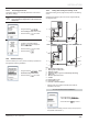
10.8.2 Heating circuit adjustment
2
3
1
4
Key
1 Speed control
2 Speed II (factory setting)
3 Speed I
4 By-pass screw
• Turn the control (1) to select pump speed I or I, in
accordance with the fl ow / pressure curve below.
• Depending on the design of the system the by-pass may
need further adjustment. It is adjusted clockwise to close and
anti-clockwise to open. This should be balanced to ensure
that it operates if the pump output is adjusted.
Hydraulic module pump fl ow / pressure curve
60
50
40
30
20
10
0
200 400 1000800
600 1200 1400
B
21 43
Key
1 Speed 2, bypass closed
2 Speed 2, bypass opened
3 Speed 1, bypass closed
4 Speed 1, bypass opened
A Available pressure (kPa)
B Flow within the circuit (l/h)
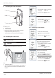
10.8.3 Venting the HP circuit
The venting of the HP circuit allows you to purge any air in the
HP circuit.
i
If the domestic hot water cylinder option is installed
on the system, reposition the kit 3-way valve to the
AUTO position.
Ø14
A
B
1
3
4
1
2
Key
1 Air trap
2 Ø 14 mm fl at wrench (Not included)
3 Hose
4 Container (Not included)
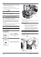
• Connect one end of the hose (3) to the trap (1).
• Insert the other end of the hose (3) into the container (4) in order
to recover any residual glycol during the venting of the circuit.
• Using the buttons ,
select Vent HP circuit on the screen.
• Press the button
to confi rm.
• Confi rm with the button in
order to begin the venting process.
You can start the heating circuit bleed at
the same time.