
Manual


0020096321_00 - 07/10 - Glow-worm
- 18 -
INSTALLATION
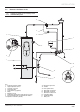
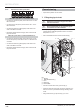
6.4.4 Connection of the 2 port valve
13
LN
230V~
13
LN
REL1
13
LN
REL2
13
LN
REL3
12
LN
REL4
12
LN
REL5
12
LN
IN1
When the 2 port valve is connected to REL3:
• Connect the neutral wire (blue) of the valve to the “N” of the
REL3 connector.
• Connect the live wire (brown) of the valve to the “L” of the
REL3 connector.
• Connect the earth wire (yellow/green) of the valve to the
earth of the REL3 connector.
• Electrically insulate the red and grey wires of the valve as
they are not used.
When the 2 port valve is connected to REL4 or 5:
• Connect the neutral wire (blue) of the valve to the “N” and
the live wire (brown) of the valve to the “L” of the REL4 or 5
connector.
• Connect the earth wire (yellow/green) of the valve to the
earth of the REL3 connector.
• Electrically insulate the red and grey wires of the valve as
they are not used.
Commissioning
• Open all the hydraulic circuits’ valves.
7 Filling the glycol circuit
b
Warning! Do not dispose of glycol into drains
and the environment.
b
We recommend that you use propylene glycol
enriched with corrosive inhibitors.
• Mix 1 part propylene glycol with 2 parts water. This
mixture ensures antifreeze protection down to an exterior
temperature of -15 °C.
• Use an antifreeze test kit to ensure accurate dosing.
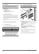
Ø14
A
B
1
3
4
1
2
Key
1 Air trap
2 Ø 14 mm fl at wrench (*)
3 Hose
4 Deposit (*)
(*) Not included
• Connect one end of the hose (3) to the trap (1).
• Insert the other end of the hose (3) into the container (4) in
order to recover any residual brine during the fi lling of the
circuit.
• Using a fl at wrench (2), open the trap (1) a ¼ turn.