
Manual


0020096321_00 - 07/10 - Glow-worm
- 16 -
INSTALLATION
6.3 Hydraulic module
• Connect the hydraulic module to an electrical panel via an
independent protective system (32A differential breaker with
a separation of at least 3mm between all contacts).
Additional protection may be required during installation to
ensure overvoltage category II.
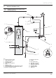
EBUS Connection
1
Key
1 Ebus connection terminal
• Connect a 2 x 0.75 mm ² cable to the hydraulic module’s
BUS terminal (2).
• Connect the Ebus cable to the Systempro control unit.
230V Connection
• Connect a 3 x 4 mm ² cable to the hydraulic module’s power
terminal 230V (1).
• Connect the hydraulic module’s power cable to the
installation’s electrical panel: single-phase network 230V +
neutral + earth.
6.4 Systempro control unit
• The electrical installation in the dwelling must permit the
power supply to the equipment to be isolated by a double
pole isolation switch and be fused. The double pole isolation
switch must incorporate a gap of 3mm between the contacts.
• Use a power cable suitable for the mains connection,
minimum 0.75 mm. If the cable is damaged, it must be
replaced by a qualifi ed engineer.
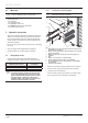
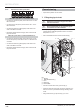
6.4.1 Wiring to the Systempro control unit
D
C
B
E
A
5
1
2
3
4
Key
1 230 V power cable
2 Break out tab
3 Anti-tamper connection
4 Power connection
5 Control unit
• Gently remove the break out tab (2) from the control unit with
pliers (A).
• Connect the control unit following the order (B) to (D).
• Pass the power cable (1) through the anti-tamper connector
(3).
• Connect the power supply to the 230 V connector (4)
following the instructions given on the connector.
• Tighten the power cable (1) in the anti-tamper connector (3).