
Manual


0020096321_00 - 07/10 - Glow-worm
- 11 -
INSTALLATION
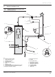
5.1.2 Connection to the hydraulic module
b
Insulate the pipes with an UV- and high-
temperature-resistant insulation.
7
5
6
1
2
3
4
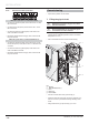
Key
1 Insulation (not supplied
2 Heat pump return circuit
3 Return connection (Ø ¾") to the heat pump
4 Return circuit ¼ turn shut-off valve in the direction of the heat
pump (not included)
5 Flow heat pump connection (Ø ¾") to the building
6 Flow heat pump circuit to the building
7 Filter (not supplied)
• Install a fi lter to the circuit returning to the heat pump. Install
it between the 2 shut-off valves in order to be able to remove
it from the circuit and clean it periodically.
• Connect the fl ow heat pump circuit (6).
• Connect the return circuit (2) to the heat pump.
5.1.3 Connection of the domestic hot water
cylinder (option)
• Refer to the instructions supplied with the 3-way valve
and the domestic hot water cylinder for their hydraulic
connections to the heat pump circuit.
i
The pressure loss of the 3-way valve has an
equivalent length tubes ¾ " or 1" for 2m.
• Deduce the pressure loss from the 3-way valve compared to
the authorized max. linear distance of the heat pump circuit.
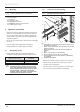
5.1.4 Removal of condensate
When the heat pump is operational, it will produce condensation
that needs to be drained off.
1
2
3
A
1
3
2
B
Key
A Confi guration with inclination to the left
B Confi guration with inclination to the right
1 Heat pump
2 Plug
3 Drainage elbow
• Insert the drainage elbow (3) and pipe into the correct
opening depending on the angle of the heat pump.
• Seal off the other opening with the supplied plug (2).