STANDALONE System Installation Standalone system for heating and hot water www.glow-worm.co.
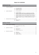
TABLE OF CONTENTS I NTRO DUCT I O N 1 Instructions guidance .........................................................................................................................3 1.1 1.2 1.3 1.4 2 System description.............................................................................................................................3 2.1 2.2 2.3 2.4 2.5 3 Product documentation........................................................................................... 3 Associated documents ...
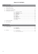
TABLE OF CONTENTS CO M MI S S I ON I N G 7 Filling the glycol circuit .....................................................................................................................18 8 Activating the heat pump .................................................................................................................19 9 Activating the room thermostat ........................................................................................................20 10 Activating the control unit .
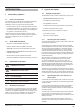
INTRODUCTION INTRODUCTION 2 2.1 1 Instructions guidance 1.1 Product documentation The instructions are an integral part of the system appliances and must be handed to the user on completion of the installation in order to comply with the current regulation. • Carefully read the manual, to understand all the information to enable safe installation, use and servicing. No liability can be accepted in the event of damage for not complying with the guidance in this instruction manual.
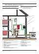
INTRODUCTION 2.2 i Example of Installation – Diagram 4 (4.1) : Standalone with 1 low heating temperature zone (3040°C) or 1 middle heating temperature zone (< 60°C) Refer to the chapters “Hydraulic connection” and “Electrical Connection” to connect the system. b This diagram shows the case of an installation with a single zone low temperature heating floor (= outlet temperature < 40°C).
INTRODUCTION 2.3 i Example of Installation – Diagram 4 (4.2) : Standalone with 2 low heating temperature zones (3040°C) or 2 middle heating temperature zones (< 60°C) Refer to the chapters “Hydraulic connection” and “Electrical Connection” to connect the system. b This diagram shows the case of an installation with a dual zone low temperature heating floor (= outlet temperature < 40°C). Zones must be same temperatures.
INTRODUCTION 2.4 i Example of Installation – Diagram 4 (4.3) : Standalone + with 3 low heating temperature zones (30-40°C) or 3 middle heating temperature zones (< 60°C) b Refer to the chapters “Hydraulic connection” and “Electrical Connection” to connect the system. This diagram shows the case of an installation with a three zone low temperature heating floor (= outlet temperature < 40°C). Zones must be same temperatures.
INTRODUCTION 2.5 Example of Installation – Diagram 4 : Standalone with Domestic Hot Water cylinder i Refer to the chapters “Hydraulic connection” and “Electrical Connection” to connect the system.
INTRODUCTION 3 R410A Refrigerant Fluid Safety instructions and regulations 3.1 e Safety instructions Incorrect installation can cause electric shock or appliance damage. • Never disable security devices and do not try to adjust them. • Be sure to consider the following handling techniques and precautions: - Grip the appliance at its base - Use safety clothing where appropriate, e.g. gloves, safety footwear. • Ensure safe lifting techniques are used: - Keep back straight.
INTRODUCTION Chapter - System description). Connect the overheat safety device to the electric supply for the module circuit board (refer to the module installation manual). INSTALLATION 4 Water treatment System appliance installation 4.1 4.1.1 Recommendations before installing Heating circuit design General The heat transmitters may be low temperature (eg underfloor heating or high temperature (radiator...).
INSTALLATION 4.2 5.1.1 Mounting i Install the Systempro control unit near the hydraulic module to facilitate system commissioning. • Consult the corresponding installation manual and install the following elements: - the heat pump, - the hydraulic module, - the Systempro control unit, - the Climapro2 wireless room thermostat, - the wireless outdoor sensor. b 4 Connection to the heat pump Insulate the pipes with an UV- and hightemperature-resistant insulation.
INSTALLATION 5.1.2 b Connection to the hydraulic module 5.1.4 Removal of condensate When the heat pump is operational, it will produce condensation that needs to be drained off. Insulate the pipes with an UV- and hightemperature-resistant insulation.
INSTALLATION 5.2 5.2.1 i Heating circuit Connection from the hydraulic module to the heating circuit Make the connection limiting the load losses to a minimum (the circuit should be as short as possible, avoid bends and narrow sections...).
INSTALLATION 5.3 b Domestic Hot Water circuit The motorised 2-port valve delivered with the FLUROCYL cylinder is not necessary for the STANDALONE system. 4 C 5 3 6 7 8 9 2 D 1 10 B 11 A 12 E A B 13 F Key 1 Domestic hot water cylinder 2 Upper temperature sensor 3 Hot water connection 4 Thermostat mixer 5 Legionnella loop (optional) 6 Pump 7 Expansion vessel 8 Temperature and pressure relief valve (95°C, 7 bar) 9 Pressure limiting valve (3.
INSTALLATION 5.3.1 Domestic hot water pipework • Connect the hot water outlet to the 22mm hot water connection of the cylinder. • Lay a further 22mm pipe to the first T-piece. A pipe of 15mm diameter should then be sufficient. • If the pipe is very long or several outlets are supplied, continue with another 22mm pipe. 5.3.
INSTALLATION 6 • Remove the box (2) by pulling it toward you using the handle (1). Electrical connections e Incorrect installation can cause electric shock or appliance damage. The electrical connection of the appliance must be made only by a qualified engineer. 6.2 e The appliance must be connected directly to an accessible, fixed, switched, electrical outlet. Electrical wiring Insert the Ebus 24V cable and 230V power cable in different casings.
INSTALLATION 6.3 Hydraulic module • Connect the hydraulic module to an electrical panel via an independent protective system (32A differential breaker with a separation of at least 3mm between all contacts). Additional protection may be required during installation to ensure overvoltage category II. EBUS Connection 6.4 Systempro control unit • The electrical installation in the dwelling must permit the power supply to the equipment to be isolated by a double pole isolation switch and be fused.
INSTALLATION 6.4.2 Internal connection 6.4.3 System connection • Refer to the table below for the wiring of the systempro. 230V connection (High voltage) - Diagram 4 (4.1) : Standalone with 1 low heating temperature zone (30-40°C) or 1 middle heating temperature zone (< 60°C) Key Description 230V~ REL1 Control unit electrical supply Domestic hot water cylinder 3-way valve 16A power relay for the domestic hot water cylinder electric heater (not supplied) 3 x 0.75 mm² 3 x 0.
INSTALLATION Connection of the 2 port valve REL3 L N 1 3 N REL4 REL5 L 3 REL2 L N 1 N 1 3 L L N 1 2 REL1 N L IN1 N 1 2 230V~ Commissioning L • Open all the hydraulic circuits’ valves. 2 1 3 6.4.4 1 When the 2 port valve is connected to REL3: • Connect the neutral wire (blue) of the valve to the “N” of the REL3 connector. • Connect the live wire (brown) of the valve to the “L” of the REL3 connector.
INSTALLATION • Close the valve (5) in (B) position and stop the filling pump. B A 4 i If the domestic hot water cylinder option is installed on the system, reposition the kit 3-way valve to the AUTO position i The level of glycol may decrease during the first month following the commissioning of the installation. It may also vary in accordance with the outdoor temperature. Any residue of glycol solution should be kept in an appropriate container to be re-used for the next filling.
INSTALLATION 9 Activating the room thermostat • Use the buttons a language. 3 • Press the button to select to confirm. 2 • Enter the installer access code 96 with the buttons . • Press the button to confirm. 1 Key 1 Battery cover 2 Protective cover 3 Room thermostat • Remove the protective cover (2) located in the battery compartment following the order (A) to (C). • The main screen of the room thermostat is displayed. 10.
INSTALLATION This screen is only displayed if you answered “YES” to the previous question. • Select number of heating zones present on the system using the buttons . 10.2 e • Set the control box switch to the Off (O) position. to confirm. • Using the buttons , select DHW cylinder on the screen, if the option is installed. • Press the button To check or modify a connection: • Set the circuit breaker located on the electrical panel and connected to the control box to the Off position.
INSTALLATION 10.4 Thermostat(s) 10.5 Outdoor sensor • Using the buttons , select Roomstat(s) on the screen. • Press the button • Using the buttons , select Outdoor sensor on the screen. to confirm. • Press the button • Using the buttons , select the area controlled by the room thermostat. • Press the button to confirm. • Using the buttons , select Connection on the screen. • Press the button to confirm. to confirm. On the room thermostat: • Press the button seconds.
INSTALLATION • Using the buttons , select External T ºC correction on the screen. • Press the button The automatic test will start. to confirm. The results appear in seconds, indicating the status of each component. This setting is automatically modified in the installer room thermostat menu. - If the connection is not correct, the message "Not OK" appears opposite the component. In this case, check the connections. • Increase or decrease with the to display the buttons desired correction.
INSTALLATION 10.7.2 This menu allows you to adjust the installation’s maximum heating output temperature (value adjustable between 30 ° C and 80 ° C - factory setting: 73°C). • Press the button . • Press the button . i The lower the temperature of the hot water, the more economical the heat pump. This menu allows you to adjust the maximum hot water temperature (value adjustable between 35 °C and 65 °C factory setting: 65°C). , • Using the buttons select Hot water on the screen.
INSTALLATION 10.7.5 Resetting parameters 10.8.1 This feature allows you to reset the parameters of the control unit (factory setting). b The resetting of factory settings is irreversible. Any customised configuration of the control unit will be lost. • Using the buttons , select Settings reset on the screen. • Press the button Filling and venting the heating circuit Venting the heating circuit purges the air present in the heating circuit.
INSTALLATION The screen shows the pressure measured in the system. • Using the buttons , select Vent heating circuit on the screen. • Press the button to confirm. • Open the taps on the module hydraulic jig and the installation domestic cold water inlet tap. • Activate filling mode by pressing the . button • Open the taps on the module hydraulic jig and the installation domestic cold water inlet tap. The screen displays the pressure measured in the system and that installation filling is in progress.
INSTALLATION b 10.8.2 10.8.3 When venting is complete, close the different heating circuit air vent. Venting the HP circuit The venting of the HP circuit allows you to purge any air in the HP circuit. Heating circuit adjustment i 3 If the domestic hot water cylinder option is installed on the system, reposition the kit 3-way valve to the AUTO position.
INSTALLATION • Using a flat wrench (2), open the trap (1) a ¼ turn in order to remove the air present in the glycol circuit, then close it quickly (in order to avoid emptying the circuit). The venting process is carried out for 15 minutes. • Repeat this last operation at the end of the venting procedure. • Press the button . b The venting may result in a drop in the glycol circuit pressure. b When venting is complete, make sure that the various heating circuit air vent are open.
INSTALLATION "Heat pump" flow / pressure curve 1 10.9.1 i 2 60 Information on the heat pump Refer to "Troubleshooting> Heat pump status" for a description of the status report displayed on the screen. 50 40 30 • Using the buttons , select Heat pump on the screen. 20 10 0 • Press the button 300 600 900 1200 Key 1 With water 20°C 2 With glycol solution (mix at 30%) at 20°C A Available pressure (kPa) B Flow within the circuit (l/h) 10.
INSTALLATION 10.9.3 Information on heating zone 10.10 Options • Using the buttons , select Heating zone on the screen. • Press the button • Using the buttons , select Parameters on the screen. to confirm. This menu allows you to: This screen is only displayed if you have installed more than one heating zone. - change the language of the control unit menus • Select the zone you want to consult . using the buttons • Press the button - adjust the brightness and contrast of the screen to confirm.
INSTALLATION - the batteries are not exhausted. If so, replace them with fresh batteries. i If the signal quality does not improve, move the thermostat to limit distances and obstacles. • Repeat these operations for each room thermostat. 10.12.2 Reinitialisation of fault log If the control unit displays "OK" for all appliances, no particular action is required. • If the control unit indicates , press the button .
MAINTENANCE MAINTENANCE 13 Trouble-shooting 13.1 Fault diagnosis The following checks should be performed before proceeding onto specific diagnostics: - Make sure that the electricity supply has not been interrupted and that the appliance is connected correctly. - Ensure that the isolating valves are open. - Check that all external controls are connected correctly. 13.2 i 13.2.
MAINTENANCE 13.2.2 Heat pump fault codes • Consult the heat pump installation manual for information about the fault codes. 13.3 Heat pump status • Consult the heat pump installation manual for information about the status codes.
MAINTENANCE Heating zones test i This menu is used to activate the domestic hot water tank electric heater. The heating zones can only be tested if you have installed multiple zone valves. , • Using the buttons select DHW cylinder elec. resist. on the screen. • Press the button to confirm. • Using the buttons , select Zones on the screen. • Press the button to confirm. The domestic hot water tank electric heater starts. • To disable the test, press the button .
0020096321_00 - 07/10 Because of our constant endeavour for improvement, details may vary slightly from those shown in these instructions. Glow-worm, Nottingham Road, Belper, Derbyshire.