
User guide


0020154078_00 - 02/13 - Glow-worm
8
APPLIANCE DESCRIPTION
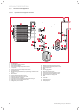
3.3 Structure of the appliance
3.3.4.1 Hydraulic and refrigerant schematic
A
B
1
2
3
5
15
16
14
17
22
18
23
19
21
24 25
26
13
12
9
10
8
7
6
11
4
20
Key
1 Ventilating fan
2 Outside air temperature sensor
3 Finned heat exchanger
4 Finned heat exchanger temperature sensor
5 4-way valve
6 Heat pump return circuit temperature sensor
7 Expansion vessel
8 Modulating high performance pump including a water fl ow rate
sensor
9 Water bleed
10 Heat pump fl ow temperature sensor
11 Draining valve for the heat pump circuit
12 Plate to plate heat exchanger
13 Temperature sensor after plate to plate heat exchanger
14 High-pressure circuit maintenance valve
15 Refrigerant pressure switch
16 Refrigerant circuit high pressure sensor
17 Compressor discharge temperature sensor
18 Rotary compressor
19 Filter
20 Anti-slugging bottle
21 Electronic expansion valve
22 Compressor suction temperature sensor
23 Low-pressure circuit maintenance valve
24 Flow rate limiter in cooling mode
25 Filter
26 Gas buff er
A Heat pump return
B Heat pump fl ow