
User guide


0020154078_00 - 02/13 - Glow-worm
6
NOTES ON THE DOCUMENTATION
2 Notes on the documentation
∙ These instructions consist of, Installation, Servicing, Fault
Finding and Replacement of Parts. The instructions are an
integral part of the appliance and must be handed to the
user on completion of the installation.
2.1 Observe other applicable documents
∙ Observe absolutely all operating and installation
instructions enclosed with the product, for the various
parts and components of the system.
2.2 Storing documents
∙ Pass these instructions and all other applicable documents
to the system user.
The system user should retain these instructions so that they
are available when required.
2.3 Validity of the instructions
These instructions apply exclusively to:
Type overview
Product Type designation Article number
Envirosorb3 8 0010011967
Envirosorb3 11 0010011968
For all system schematics and information please refer to the
heatpump system manual.
3 Appliance description
3.1 Safety devices
- The appliance is designed to operate with an outside
temperature between -20°C and 35°C in heating mode and
between -20°C and 46°C for tank heating.
- A high pressure switch limits the operation of the
appliance when the refrigerant fl uid pressure exceeds
41.5 bar (gauge pressure) (41.5 x 10
5
Pa) (relative pressure).
- When the appliance is shut down, the compressor
crankcase heater is activated below 7°C at the compressor
outlet to prevent any damage when restarting.
- If the compressor outlet temperature is below 1°C, the
appliance will not allow the compressor to start.
- A temperature sensor at the compressor outlet limits
the operation of the heat pump when the temperature
measured by this sensor is higher than the maximum
limit. This value varies depending on the evaporation and
condensation temperatures.
- The appliance is equipped with a measuring device that
checks the water fl ow rate at start-up.
- An anti-freezing protection device runs the heat pump
hydraulic pump when the hydraulic circuit temperature is
lower than 3°C. However, it is necessary to add anti-freeze
to the heat pump hydraulic circuit. Without the addition
of outside energy or in the case of a power cut, the circuit
water can drop below the freezing point.
3.2 Concept of operation
A heat pump (HP) is a thermodynamic machine which
transfers heat from one location to another. To do so, it
employs the characteristics of a refrigerant fl uid.
The system is composed of the following circuits:
- The refrigerant circuit which transfers heat to the
water circuit following the evaporation, compression,
condensation and expansion of the fl uid.
- The heating circuit.
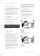
3.2.1 Heating mode
1
2
3
4
5
6
Key
1 Fin exchanger
2 Four way valve
3 Ventilating fan
4 Compressor
5 Expansion valve
6 Plate to plate heat exchanger
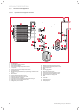
3.2.2 Defrosting mode
1
2
3
4
5
6
Key
1 Fin exchanger
2 Four way valve
3 Ventilating fan
4 Compressor