
User guide


0020154078_00 - 02/13 - Glow-worm
24
APPENDIX
11 Appendix
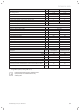
11.1 Table of Diagnosis codes
Réf.
état
Description
0 Heat pump waiting
1 Pump pre-run before heating
2 Pump pre-run correct in heating mode
3 Water temperature / heating setting compatibility test
4 Heating phase start activation
5 Pre-run of pump at maximum speed in heating
6 Pre-run of fan in heating
7 Setting the 4-way valve to the heating position
8 Setting electronic expansion valve to the heating position
9 Compressor start request in heating mode
10 Heat pump in heating mode
11 Heat pump in domestic hot water heating mode
12 Water temperature exceeded in heating mode
13
Water temperature exceeded in domestic hot water heating
mode
14 Pump post-run after heating
15 Pump pre-run before de-icing
16 Heat pump in de-icing mode
17 Pump post-run after de-icing
18 Pump remote controlled (top-up)
19 Compressor oil temperature too low for start-up
30 Pump pre-run before cooling
31 Pump pre-run correct in cooling
32 Water temperature / cooling setting compatibility test
33 Cooling phase start activation
34 Pre-run of pump at maximum speed
35 Fan pre-run
36 Setting 4-way valve to cooling position
37 Setting electronic expansion valve to the cooling position
38 Compressor start request in cooling mode
39 Heat pump in cooling mode
40 Water temperature exceeded in cooling mode
41 Post-run of the pump after cooling
50 Pressure balance fault
51 Pressure switch fault
52 Pressure envelop fault detected
53 Start envelop not ok error detected
54 Loss of “cheap tariff ” supply block
55 Refrigerant circuit pressure out of range: HP/LP ratio too low
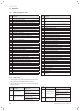
Réf.
état
Description
56
Refrigerant circuit pressure out of range: condensation too
low
57
Refrigerant circuit pressure out of range: evaporation too
high
58
Refrigerant circuit pressure out of range: condensation too
high
59 Refrigerant circuit pressure too low
60 Compressor outlet over-heat
61 Compressor inlet temperature sensor fault
62 Compressor outlet temperature sensor fault
63 Plate exchanger temperature sensor fault
64 Fin exchanger temperature sensor fault
65 Outside air temperature sensor fault
66 Flow water temperature sensor fault
67 Return water temperature sensor fault
68 Refrigerant circuit high pressure sensor fault
69 Low voltage fault – inverter box bus
70 Inverter box disconnected fault
71 Inverter box over-heat fault
72 Inverter box current-voltage fault
73 Under power fault – inverter box bus
74 Overvoltage power fault – inverter box bus
75 Inverter box internal fault
76 Inverter box radiator sensor fault
77 Inverter box overload fault
78 “FMU” fan circuit board fault
79 e-BUS communications fault
80 Water fl ow rate fault
81 Communications fault with the inverter box
82 Compressor overcurrent fault
83 Water fl ow temperature too high
84 Electronic expansion valve fault
85 Fan speed too low
86 Detection of potential icing in the plate exchanger
87 Water ΔT too high fault
88 Coding resistor fault
89 Heated floor overheating safety device fault
90 4-way valve fault
99
Appliance fault, refer to section 7.2 to see the corresponding
error code.
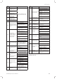
11.2 Fault codes
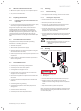
∙ Read the heat pump status code number from the control
box screen (see control box installation manual).
∙ Refer to the table in section 11.1 of this manual to see the
heat pump state.
Fault
codes
Description Possible cause
37 Fan speed too low.
There is an obstacle in the heat
pump’s air fl ow.
The fan motor is defective or
disconnected.
42
Product coding resistor
error.
The product coding resistance is
missing or defective.
The resistance value is outside
the authorised limits.
Fault
codes
Description Possible cause
86
The floor heating over
heat contact is open.
The heated fl oor temperature is
too high.
The fl ow rate of the installation
hydraulic circuit is too low.
The heated fl oor circuits are
closed.
103
Spare part
identifi cation error.
The circuit board or inverter driver
used as a replacement part does
not correspond to the product.