
User guide

0020154078_00 - 02/13 - Glow-worm
19
MAINTENANCE
6.1 Observe maintenance intervals
∙ Maintain the product only if you are a competent person.
∙ Carry out annual maintenance.
6.2 Preparing maintenance
6.2.1 Providing spare parts for maintenance and
repair work
∙ In case you need spare parts during maintenance or repair,
exclusively use genuine Glow Worm spare parts.
The genuine component parts of the product have been
certifi ed together with the product in the course of the
CE conformity check. If you do NOT use certifi ed genuine
Glow Worm spare parts during maintenance or repair, the
CE conformity of the product will expire. That is why we
imperatively recommend to install genuine Glow Worm spare
parts.
6.3 Pre-maintenance instructions
Comply with the basic safety rules before performing
maintenance or installing spare parts.
∙ Shut down the system.
∙ Switch off the system electrical supply.
∙ Isolate the hydraulic circuit from the appliance using the
shut-off valves where necessary.
∙ Drain the appliance if you need to replace hydraulic circuit
components.
∙ Protect all electric components from water if you have to
work on the appliance.
6.4 Annual Maintenance
∙ Check the proper functioning of safety devices.
∙ Check the pressure of the water system.
∙ Check tightness of refrigerant circuit.
∙ Check that there are no traces of rust or oil around the
refrigerant circuit’s components.
∙ Ensure that the appliance’s components are neither worn
nor broken.
∙ Check that the wires are fi rmly attached to the electrical
terminals.
∙ Check the appliance’s grounding.
∙ Check the fl ow temperature of the heat pump and the
setting points.
∙ Check that the fan rotates freely.
∙ Check the pressure of the expansion vessel.
6.5 Cleaning
6.5.1 External cleaning
∙ If the appliance needs cleaning, refer to the user manual.
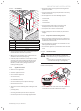
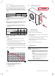
6.5.2 Cleaning the components
∙ Check the absence of ice on the compressor.
∙ Remove any dust from electronic boxes.
∙ Clean the air / refrigerant battery and make sure that air
circulates between the fi ns and around the unit.
∙ Check that condensates can properly drain from the heat
pump by removing the adapter located under the heat
pump (turn it a ¼ turn to unlock).
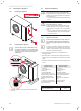
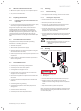
∙ Clean the evaporator on both sides using a brush with soft
bristles. Remove the fan blades and the rear grill before
cleaning.
a
Warning!
Risk of minor injury.
Handling the fan blades and grill can cause cuts.
• Wear protective gloves to perform this
operation.
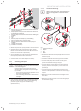
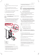
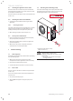
6.6 Draining
∙ Cut off the appliance’s electricity supply.
2
1
14mm
Key
1 Hydraulic circuit venting valve
2 Draining hose
∙ Close the shut-off valves located behind the heat pump.
∙ Engage a hose (2) to the venting valve (1) or place a
container under the venting valve (1) to drain the hydraulic
circuit.
∙ Open the bleed valve (1) with a fl at spanner.
Note: if necessary, the heating installation can be drained via
this bleed valve by opening the shutoff valves located at the
rear of the heat pump.