
User guide

0020154078_00 - 02/13 - Glow-worm
17
START-UP
5 Start-up
∙ Refer to the operating instructions before starting the
product.
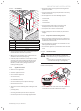
∙ Check that the diff erential breaker is installed.
∙ Check that the hydraulic and electrical connections are
correct.
∙ Check that the fi lter on the heat pump return is installed.
∙ Check the airtightness of the connections.
∙ Open all the hydraulic circuits’ valves.
5.1 Filling the hydraulic circuit
i
We recommend that you use propylene enriched
with corrosive inhibitors.
∙ Do not dispose of glycol into drains and the environment.
∙ Mix a maximum of 50% of propylene or ethylene glycol
with water. The mixture must provide anti-freezing
protection for the heat pump hydraulic circuit.
∙ Use an antifreeze test kit to ensure accurate dosing.
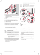
A
B
2
1
4
3
14mm
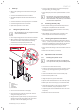
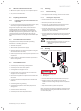
Key
1 Air trap
2 Flat wrench (*)
3 Hose
4 Deposit (*)
(*) Not included
∙ Connect one end of the hose to the tap (A).
∙ Insert the other end of the hose (3) into the container
during the venting of the circuit.
∙ Using a fl at wrench, open the tap a ¼ turn (B) in order to
remove the air present in the glycol circuit, then close it
quickly (in order to avoid emptying the circuit).
∙ In order to bleed the hydraulic circuit of the heat pump
during the fi lling, use a fi lling pump.
∙ Put the heat pump circuit under pressure between 1.5 and 2
bars.
i
The hydraulic circuit pressure may decrease dur-
ing the first month following the commissioning
of the installation. It may also vary in accordance
with the outdoor temperature.
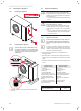
5.2 Activating the heat pump
∙ Ensure that the setting of the maximum temperature of
heating fl ow is compatible with the installation.
∙ Refer to the system installation manual in order to fully
activate the installation.
∙ Switch ON the circuit breaker which is located on the
electrical panel and connected to the heat pump.
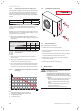
5.3 Checking the operation of the device
∙ Ensure that the external regulators (thermostat, external
sensor, ...) send a request to the heat pump. In the case of
a multi-zone confi guration, perform the test zone by zone
and ensure that the appropriate zone gets warmer.
∙ Ensure that all the heating circuit’s thermostatic valves are
open.
∙ Balance the heat emitters, if necessary.
5.4 Adjustment of HP circuit fl ow
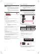
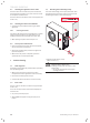
5.4.1 Bleeding the hydraulic circuit
i
If the swimming pool option is installed on the
circuit put the kit's 3 way valve on AUTO position.
∙ Connect one end of the hose to the tap.
∙ Insert the other end of the hose into the container in order
to recover any residual glycol during the venting of the
circuit.
∙ Close the shutoff valves at the rear of the heat pump.
∙ Pressurise the hydraulic circuit.
∙ Using a fl at spanner, open the bleed valve.
∙ Open the lower shutoff valve at the rear of the heat pump.
∙ When liquid comes out of the pipe, close the bleed valve
∙ Check that the hydraulic circuit pressure is between 1.5
and 2 bar. Otherwise, top up the hydraulic circuit.
∙ Completely open the two shutoff valves at the rear of the
heat pump.
∙ Remove the hose and the container.