
User guide

0020154078_00 - 02/13 - Glow-worm
15
MOUNTING AND INSTALLATION
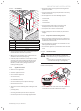
Envirosorb
3
8 Envirosorb
3
11
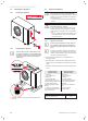
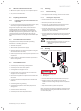
Recommended cable size
eBus
2 x 0.75 mm² 2 x 0.75 mm²
Recommended cable size
eBUS + FLOOR H
4 x 0.75 mm² 4 x 0.75 mm²
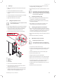
∙ Pass the cables through the heat pump cable gland (see
section 4.4.3).
∙ Connect the e-BUS cable to the system control box
complying with the polarity ±.
∙ If a manual reset floor heating protection device (55°C)
is installed on the heating circuit outlet, remove the link
from the terminal (2) and then connect the floor heating
protection device to this terminal.
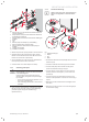
4.4.3 Cable routing
b
Caution!
Risk of appliance malfunction
If the very low voltage and low voltage cables are
in the same duct, the very low voltage signal will
be disturbed by the low voltage.
• Run the very low voltage and low voltage
cables in different ducts.
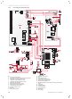
12
34
56
7
8910
11
12
13
14
15
16
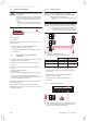
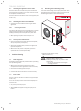
A
B
C
D
ØA
ØA
eBus
230V
Key
eBUS e-BUS cable and fl oor heating protection device cable
gland
230V 230V supply cable gland
∙ Measure the diameter of the cable (A).
∙ Use a drill of the same diameter as the cable and drill
through the cable gland seal (B).
∙ Pass the cable through the cable gland provided for this
purpose (C)
∙ Set the cable gland with 2 fl at spanners (D) to get it tight.