
User guide

0020154078_00 - 02/13 - Glow-worm
13
MOUNTING AND INSTALLATION
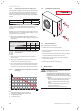
0.75m min.
1
2
3
8
5
4
4
5
6
7
9
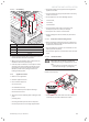
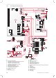
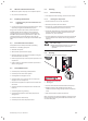
Key
1 Return circuit ¼ turn shut-off valve in the direction of the heat
pump (not included) (*)
2 Heat pump fl ow circuit ¼ turn shut-off valve in the direction of
the building (not included) (*)
3 Flow heat pump circuit hose in the direction of the building (not
supplied)
4 O ring
5 Cap
6 Flow heat pump connection (Ø 1¼") to the building
7 Return connection (Ø 1¼") to the heat pump
8 Return circuit hose in the direction of the heat pump (not
supplied)
9 Insulation (not supplied)
(*) Available as an accessory
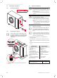
∙ Remove the protection caps (4) located on the connections.
∙ Install the fi lter on the heat pump return pipe. Install it
between 2 shut-off valves in order to be able to remove if
from the circuit and clean it periodically.
∙ Connect a fl exible pipe + the O ring and a shutoff valve to
the heat pump outlet and return connectors.
∙ Check that there are no leaks. Repair if necessary.
4.3.2 Swimming pool option
b
Caution!
Risk of damage in the case of a direct connection
to the swimming pool.
If the heat pump is connected directly to the
swimming pool, the appliance may be damaged
by corrosion.
• Do not connect the heat pump hydraulic circuit
directly to a swimming pool
• Use a swimming pool kit with an external heat
exchanger.
∙ In the case of an installation with a swimming pool option,
take into account the water volume up to the swimming
pool kit for proper sizing of the installation (e.g.:
expansion tanks...).
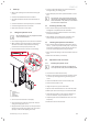
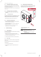
4.3.3 Condensate discharge
i
Observe these instructions, the legal directives
and the local regulations to evacuate conden-
sates.
550
102,5
Ø25
A
B
D
C
1
2
4
3
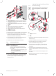
Key
1 Condensate drain pipe
2 Adapter
3 Clip
4 Elbow
∙ Assemble the elbow and the adapter (A) and then secure it
with the clip (B).
∙ Install the condensate evacuation pipe onto the elbow.
∙ Insert the heat pump electric heater into the pipe to
prevent condensates freezing in the pipe.
∙ Insert the adapter into the hole in the base of the heat
pump (C), then turn the adapter a ¼ turn to lock it into
position (D).
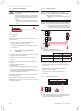
∙ Connect the pipe to the condensate evacuation circuit
either in a bed of pebbles or connected to a drain using a
siphon.
∙ Make sure that the condensate does not stagnate in the
drain hose.
∙ Make sure that the drain hose is not connected tightly to
the waste water piping.