The energy you need Installation manual Envirosorb3 8 Envirosorb3 11
TABLE OF CONTENTS 1 Safety....................................................... 3 7 Trouble-shooting .................................... 20 1.1 Symbols used ......................................................... 3 7.1 Fault diagnosis...................................................... 20 1.2 Qualifications ......................................................... 3 7.2 Error codes ........................................................... 20 1.3 General safety advices .................
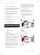
SAFETY 1 Safety 1.1 1.3.3 Symbols used The warning notes are classified in accordance with the severity of the possible danger using the following warning signs and signal words. Warning symbol Explanation a e a b 1.2 Danger! Immediate danger to life or risk of severe personal injury. Danger! Risk of death from electric shock. Warning! Risk of minor personal injury. Caution! Risk of material or environmental damage. Qualifications Any work carried out must be by suitably qualified personnel.
SAFETY ∙ Welding is to be carried out with nitrogen and the circuit’s air-tightness is to be tested under pressure, with nitrogen. ∙ Refilling must be done at the liquid phase. ∙ In case of leakage, do not add fluid: drain the remaining fluid from the circuit and eliminate, in accordance with the applicable regulations. 1.6 Rules and regulations On installing and commissioning the appliance you must adhere to the technical rules, standards and provisions in effect at the time. 1.
SAFETY 1.9 1.9.1 Regulations Statutory requirements IMPORTANT Where no British Standards exists, materials and equipment should be fit for their purpose and of suitable quality and workmanship. The installation of this appliance must be carried out by a competent person in accordance the rules in force in the countries of destination. Manufacturer’s instructions must not be taken as overriding statutory requirements.
NOTES ON THE DOCUMENTATION 2 Notes on the documentation ∙ These instructions consist of, Installation, Servicing, Fault Finding and Replacement of Parts. The instructions are an integral part of the appliance and must be handed to the user on completion of the installation. 2.1 Observe other applicable documents ∙ Observe absolutely all operating and installation instructions enclosed with the product, for the various parts and components of the system. 2.
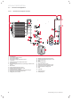
APPLIANCE DESCRIPTION 5 6 Expansion valve Plate to plate heat exchanger 3.2.3 70 60 50 Operating limits in heating mode A [-15;53] [28;63] [35;63] [2;63] [46;58] [35;58] [-20;43] 40 30 [35;26] [46;26] 20 10 [-20;15] 0 -20 [28;15] -10 0 10 20 [35;15] 30 40 50 B Key A B Heating operating limits Domestic hot water operating limits Water temperature Air temperature 3.2.4 Permitted hydraulic configurations 3.2.4.1 Direct connection to the installation heating circuit 3.2.4.
APPLIANCE DESCRIPTION 3.3 Structure of the appliance 3.3.4.
MOUNTING AND INSTALLATION 3.4 Type designation and serial number Data plate location: Mounting and installation 4.1 1 1 Key 1 4 Data plate Preparing mounting and installation 4.1.1 Delivery, transport and installation on site 4.1.1.1 Transport a Warning! Risk of injuries due to big carrying loads. Too big carrying loads can cause injuries, e.g. on the backbone. • Observe all relevant laws and other prescriptions when carrying heavy products.
MOUNTING AND INSTALLATION ∙ Use the transport strap (1) to move the appliance. 4.1.1.3 Installation pipework must be designed and installed to ensure venting of air from the system is possible. ∙ Check the contents of the packages. The appliance is delivered with a bag of documents and a box of accessories which contains the following items: ∙ Only lift the appliance from the rear and the side containing the hydraulic connectors.
MOUNTING AND INSTALLATION 4.1.2.2 Accessibility ∙ Avoid areas exposed to strong winds directed against the appliance’s air outlet. ∙ Do not install the fan facing nearby windows. If necessary, install a noise barrier. B A ∙ Set the appliance on one of the following supports: - concrete slabs, C E D A - crane beam, - concrete blocks. ∙ Do not expose the heat pump to corrosive or dusty atmospheres (near to dirt roads, for example). ∙ Do not place near to stale air extraction fans.
MOUNTING AND INSTALLATION 4.2 Mounting the appliance 4.2.1 4.3 Opening the appliance Hydraulic installation b Caution! Risk of damage caused by contaminated lines! Foreign bodies such as welding remnants, sealing residue or dirt in the supply lines can cause damage to the product. • Flush the supply lines thoroughly before installation. b Caution! Risk of damage due to corrosion.
MOUNTING AND INSTALLATION 6 5 7 4 5 4.3.3 Condensate discharge i Observe these instructions, the legal directives and the local regulations to evacuate condensates. 3 2 1 4 8 D 9 n. 5m 0.
MOUNTING AND INSTALLATION 4.4 Electrical Installation e Danger! Risk of electric shock due to an improper electrical connection! Improper electrical connection can cause electric shock or might negatively affect the operational safety of the product and might cause material damage. • The electrical connection of the product must be carried out only by a suitably qualified person. 1 4.4.1.1 230V heat pump b Caution! Risk of damage from too great voltage.
MOUNTING AND INSTALLATION Envirosorb3 8 Envirosorb3 11 Recommended cable size eBus 2 x 0.75 mm² 2 x 0.75 mm² Recommended cable size eBUS + FLOOR H 4 x 0.75 mm² 4 x 0.75 mm² ∙ Pass the cables through the heat pump cable gland (see section 4.4.3). ∙ Connect the e-BUS cable to the system control box complying with the polarity ±.
MOUNTING AND INSTALLATION Circuit diagram (230V heat pump) 4 3 X30 X60 X24 12 X60DA 14 X26 10 9 8 7 6 5 4 3 2 1 20 19 18 17 16 15 14 13 12 11 HMU X14 11 1 N L X21 4567 15 16 X700 X22 18 19 N L X13 N L X16 20 230V~ N L X11 X1 FMU 17 X15 X 1 3 9 8 7 6 5 4 3 2 1 18 17 16 15 14 13 12 11 10 X23 24V= 24V= BUS S20 S21 5 4 3 2 1 10 9 8 7 6 13 2 1 4.4.
START-UP 5 Start-up ∙ In order to bleed the hydraulic circuit of the heat pump during the filling, use a filling pump. ∙ Refer to the operating instructions before starting the product. ∙ Put the heat pump circuit under pressure between 1.5 and 2 bars. ∙ Check that the differential breaker is installed. ∙ Check that the hydraulic and electrical connections are correct. ∙ Check that the filter on the heat pump return is installed.
MAINTENANCE 5.4.2 5.5 Adjusting the hydraulic circuit flow rate Installation of side panel The heat pump is designed to operate above a minimum flow rate. If the heat pump functions at a minimum flow rate, this will result in a loss of power and performance. The heating comfort will still be guaranteed but the energy savings will be reduced.
MAINTENANCE 6.1 Observe maintenance intervals ∙ Maintain the product only if you are a competent person. ∙ Carry out annual maintenance. 6.2 6.2.1 Preparing maintenance Providing spare parts for maintenance and repair work 6.5 Cleaning 6.5.1 External cleaning ∙ If the appliance needs cleaning, refer to the user manual. 6.5.2 Cleaning the components ∙ Check the absence of ice on the compressor. ∙ Remove any dust from electronic boxes.
TROUBLE-SHOOTING 6.7 Checking the appliance status codes The status codes can be checked at any time to know what operating phase the appliance is in. These codes can be read on the system control box screen. 7.3 Resetting the overheating safety In the case of overheating, the heat pump shuts down. Once the temperature has returned to normal, you must reset the overheating thermostat to restart the heat pump. The status codes are described in a table in the appendix (see section 11.1). 6.
DECOMMISSIONING 9 9.1 Recycling Packaging ∙ Sort the waste to separate those which can be recycled (cartons, plastics...) from those that cannot (strapping ...). ∙ Recycle the product packaging according to all relevant regulations. 9.2 Appliance ∙ Do not dispose of your product or any of its accessories in the household waste. ∙ Make sure the old unit and any accessories are disposed of properly. ∙ Observe all relevant regulations.
TECHNICAL DATA 9.3 Refrigerant fluid b Attention! Risk of pollution! This appliance contains R410-A refrigerant fluid which must never be released to the atmosphere. R410-A is a fluoride greenhouse gas covered by the Kyoto protocol. • Before discarding the appliance, correctly recover the refrigerant fluid into an appropriate container to be recycled in compliance with the regulations in force.
TECHNICAL DATA Description Unit Envirosorb3 8 Envirosorb3 11-1ph bar 3 3 Pa 3 x 10 3 x 10⁵ Minimum water flow rate l/h 380 540 Maximum water flow rate l/h 1400 1900 Expansion vesel capacity l 2 2 Capacity of the hydraulic circuit internal to the heat pump l 4 4 Minimum capacity of the complete hydraulic circuit l 21 35 Max. filling pressure.
APPENDIX 11 Appendix 11.1 Table of Diagnosis codes Réf. Description état 0 1 2 3 4 5 6 7 8 9 10 11 12 Réf.
APPENDIX Fault Description codes 514 The compressor inlet temperature sensor or connection is out. 517 The compressor outlet temperature sensor or connection is out. 519 The heating return temperature sensor or connection is out. 520 The flow heating temperature sensor or connection is out. 526 Coil sensor interrupt or short circuit. 532 536 755 537 The flow on heat pump water circuit is too low or too high (see section 5.4.2).
Subject to engineering changes 0020154078_00 - 02/13 GLOW-WORM Nottingham Road, Belper, Derbyshire. DE56 1JT www.glow-worm.co.uk Because of our constant endeavour for improvement, details may vary slightly from those shown in these instructions.