Installation and Servicing Envirosorb2 7 / 12 / 14
Table of contents INT R O D U C T I O N 1 Instructions guidance.................................................................................................................... 3 1.1 1.2 1.3 1.4 2 Appliance description.................................................................................................................... 3 2.1 2.2 2.3 2.4 2.5 3 Safety instructions...............................................................................................7 Regulations . ...............
Table of contents 13 Electrical connection................................................................................................................... 22 13.1 13.2 13.3 13.4 14 Commissioning........................................................................................................................... 27 14.1 14.2 14.3 14.4 15 Filling the glycol circuit.......................................................................................27 Activating the heat pump....................
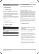
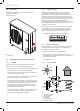
INTRODUCTION INTRODUCTION 1 Instructions guidance 1.1 Product documentation The instructions are an integral part of the appliance and must be handed to the user on completion of the installation in order to comply with the current regulation. • Carefully read the manual, to understand all the information to enable safe installation, use and servicing. No liability can be accepted in the event of damage for not complying with the guidance in this instruction manual.
INTRODUCTION 2.2 Data label 2.3.2 The data label certifies the country where the appliance is intended to be installed. Data label location: Local regulations Benchmark places responsibilities on both manufacturers and installers.
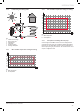
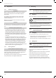
INTRODUCTION 2.4.2 In defrosting and cooling mode 2.4.4 Min. and Max. temperature settings in cooling A 20 18 16 14 12 2 10 8 6 1 4 3 2 4 0 6 5 Key 1 2 3 4 5 6 Tubular heat exchanger Reverse cycle valve Ventilating fan Compressor Pressure regulator Exchanger with plates 2.4.3 70 10 Key A Water temperature B Air temperature 2.4.5 Min. and Max. temperature settings in heating 0 20 30 40 46 50 B Principle for controlling the heat pump Control using the Glow Worm control unit.
INTRODUCTION 2.
INTRODUCTION 3 Safety instructions and regulations 3.1 e Safety instructions Incorrect installation can cause electric shock or appliance damage. • Never disable security devices and do not try to adjust them. • Be sure to consider the following handling techniques and precautions: • Grip the appliance at its base • Use safety clothing where appropriate, e.g. gloves, safety footwear. • Ensure safe lifting techniques are used: • Keep back straight. • Avoid twisting at the waist.
INTRODUCTION 3.2 3.2.1 4 Regulations Statutory requirements IMPORTANT Where no British Standards exists, materials and equipment should be fit for their purpose and of suitable quality and workmanship. The installation of this appliance must be carried out by a competent person in accordance the rules in force in the countries of destination. Recycling i 4.1 On installing and commissioning the appliance you must adhere to the technical rules, standards and provisions in effect at the time.
INTRODUCTION 5 5.1 Guarantee / Responsibility Detailed guarantee Thank you for installing a new Glow-worm appliance in your home. Glow-worm appliances are manufactured to the very highest standard so we are pleased to offer our customers a Comprehensive Guarantee. This product is guaranteed for 24 months from the date of installation or 30 months from the date of manufacture, whichever is the shorter, for parts and labour.
technical data TECHNICAL DATA i 6 This technical data is valid for a new appliance with its own heat exchangers. Envirosorb Description Unit 7 12 14 Min. operating outside temperature (in heating) °C -20 -20 -20 Max. operating outside temperature (in heating) °C 30 30 30 Specifications, with radiators (flow : 45°C, return : 40°C, outside dry temperature (wet) 7 (6)°C) Heating output kW 7.4 12.9 14 Power input kW 2.32 4.2 4.
technical data Description Unit 7 12 14 Electrical Supply voltage/frequency V/Hz Fuse 1/N/PE 230V 50Hz 15 typo D 25 typo D 25 typo D Maximum absorbed power (P max) kW 2.7 5.1 5.
INSTALLATION INSTALLATION • Do not place near to stale air extraction fans. • Allow room for electricity cables (high and low voltage). i 7 All the drawings dimensions are shown in mm. • Explain these requirements to the appliance user. 7.1.2 Discharge of condensates Appliance location 7.1 7.1.1 Heat pump location Instructions • Before choosing a site for the appliance, carefully read the safety warnings and installation manual.
INSTALLATION 7.2 Clearances -- Respect the minimum dimensions shown in the drawing above in order to ensure a correct air flow and to facilitate maintenance operations. -- Make sure that the available space is sufficient for the installation of the water system piping. 7.
INSTALLATION 8 Installing the command unit • Make sure that the materials used for performing the installation are compatible with those of the appliance. 1 • Determine the place of assembly. See the chapter "Location". 2 3 2 3 1 4 1 Key 1 Command unit 2 Wall support • Assemble the command unit (1) on the wall support (2). 9 Key 1 2 3 4 9.1 Installing the heat pump Scope of delivery Mounting screw Wall support Rawlplug Electric terminal block 2 2.1 2.
INSTALLATION 2.3 Protection against the sharp edges of the sheet metal for the cable passage (if necessary) Leak-tight seal for the cable passage (if necessary) 2.4 (x1) (x1) 3 3.1 3.2 Packet of documents Installation manual Instructions for use (x1) (x1) (x1) 4 Command unit (x1) • Check the contents of the package. 9.2 9.2.1 Recommendations before installation Design of the heating circuit The heat emitters may be either low temperature (underfloor heating, etc.
INSTALLATION 9.3.2 Envirosorb 12, Envirosorb 14 9.3.3 Command unit 326 132 908 132 1 2 3 4 5 6 7 27 9.4 136 3 9.4.1 Mounting Unpacking the appliance • Carefully remove the packaging and protections without damaging the parts of the appliance. 150 2 600 150 3 1 1 Key 1 Transport pallet 2 Attachment screws 3 Heat pump • Remove the screws from the transport pallet at the front and rear of the unit.
INSTALLATION 9.4.2 i Transportation of the appliance With regards to the Manual Handling Operations, 1992 Regulations, the following lift operation exceeds the recommended weight for a one man lift. 9.5 i Positioning the appliance With regards to the Manual Handling Operations, 1992 Regulations, the following lift operation exceeds the recommended weight for a one man lift. 2 1 1 a Warning! Two people at minimum are necessary to move the appliance.
INSTALLATION 10 Examples of installation 10.
INSTALLATION Key 1 Heat pump 2 Power supply and electrical protection for the heat pump (*) 3 Command unit for the heat pump 4 Glow Worm control unit (*) 5 Glow Worm hydraulic module (*) 6 Anti-sludge filter (*) A Flow heat pump circuit B Return heat pump circuit E Return heating circuit F Flow heating circuit H Discharge from the safety valve to a container for recovering glycol water solution (*) Not delivered with the appliance Application conditions -- Command unit used as configuration tool (see the
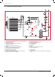
INSTALLATION 10.2 Installation with hydraulic module, DHW tank, control by control unit 2 3 230V 230V 5 4 F 6.1 E 6 7 6.2 1 9 B H A 8 4 6.2 R6.1 L5 8 1 230V 230V 5 2 3 6.
INSTALLATION Key 1 Heat pump 2 Power supply and electrical protection for the heat pump (*) 3 Power supply and electrical protection for the booster heating (*) 4 Glow Worm control unit (*) 5 Command unit for the heat pump 6 Domestic hot water tank (option) (*) 6.1 Electrical booster element 6.2 Temperature sensor for hot water tank 7 Glow Worm hydraulic module (*) 8 3-way valve (with return spring) for the domestic hot water tank (*) 9 Anti-sludge filter (*) R6.
INSTALLATION • Do not use any solvent products, due to the risk of damaging the circuit. • Only use original seals supplied with the appliance. b Make sure that mechanical connections are not overtightened. b Insulate the pipes with an UV- and high-temperatureresistant insulation. • Insulate all exposed pipework. 12 Discharge of condensate When the appliance is operational, it will produce condensation that needs to be drained off.
INSTALLATION The cables connecting the installation's electrical panel and the heat pump must be: - Suitable for a fixed installation. - weather resistant. - equipped with wires adapted to appliance’s power rating. 13.2 e Cable passage The low and mains voltage cables must be inserted in different sleeves. • Connect the heat pump to an electrical panel via an independent protection system (differential breaker with at least 3 mm between each contact). See the table below.
INSTALLATION 13.5 13.5.
INSTALLATION 13.5.2 Board of power 7kW R W 1 2 3 7CM 1 2 3 40CF P04 P05 C 3 1P.C.
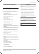
INSTALLATION 13.5.3 Board of power 12kW, 14kW + R R ED 7CM 41CF 1 2 3 1 2 3 W 8CM 45CF W P08 1 2 3 1 2 3 G P09 O A C Y G P12 P13 P21 P24 P28 P29 B P19 P20 P17 P18 CN09 CN01 CN03 CN13 1 1 42CF 2 1 CN05 3 4 R 1RV 5 46CF 1 C 2 1 1 49CF CN11 CN06 2 3 4 5 52CF 1 P R BW C O CN04 1 2 Y 1 1 CN600 C CN10 1P.C.
INSTALLATION 14 Commissioning i At the time of commissioning, complete all relevant sections of the Benchmark Checklist located on the inside back pages of this document 14.4 Heating system test • Ensure that there is a heating demand to the control unit. In the case of a multi-zone configuration, perform the test zone by zone and ensure that the appropriate zone gets warmer. • Check that the differential breaker is installed. • Ensure that all the heating circuit’s thermostatic valves are open.
INSTALLATION 15.2 Envirosorb 8 flow/pressure curves 60 50 40 30 20 10 0 15.2.1 A i 3 2 1 Appliance configuration parameters If the parameters are changed, it is important to leave the control box connected for at least 10 seconds so that the change is properly saved. • Press simultaneously on the button ( ) and (M) for 3 seconds. The parameter number is displayed and its value blinks.
INSTALLATION 15.2.2 Parameters set by the installer • Press the buttons ( ) to modify the value. This menu lets you enter the settings intended for the final user. • Press the button (M) or (OK) to confirm the parameter setting. ) and ( ) for 3 • Press simultaneously on buttons ( seconds. The parameter number is displayed and its value blinks. • Press the buttons ( • Press the button (M) to access the parameter. The value of the parameter flashes.
INSTALLATION 15.2.3 After-sales service parameters This menu lets you make adjustments to the following functions according to the appliances connected, and reset all these parameters. • Press the button (M) or (OK) to confirm the parameter setting. • Press simultaneously on button ( ) and ( ) for 3 seconds. The parameter number is displayed and its value blinks. • Perform the previous operations again for the other parameters. • Press the button (M) to access the parameter.
INSTALLATION Predefined heating curves (code 112) 60 A 9 10 11 12 -5 0 5 Key 7 8 9 10 11 12 A B 8 50 7 40 30 20 -20 -15 -10 Code Function 112 114 116 117 10 15 20 Heating graph n°7 Heating graph n°8 (factory setting) Heating graph n°9 Heating graph n°10 Heating graph n°11 Heating graph n°12 Heating flow temperature (°C) Exterior temperature (°C) B Setting Min Max Description Predefined heating curves ECO heating mode ECO cooling mode 0 = Personalised graph (see codes 118 to 121) 1
INSTALLATION Code Function 126 Configurations exterior sensor 127 Exterior temperature 128 129 130 131 132 133 134 135 136 137 138 139 140 141 142 143 144 145 - 32 - Temperature of the cooling circuit battery Compressor suction temperature Compressor discharge temperature Description Choose the type of exterior-temperature sensor: 1 = Remote sensor (connected onto terminal block 23 and 24) 2 = Sensor installed on the heat pump.
INSTALLATION Code Function Setting Min Max Description Factory setting Modifiable parameter 146 Configuration for stopping the heat pump if control by S1 contact input 1 = Immediate halt (as soon as contact S1 moves into the open position, the heat pump stops). 2 = Gradual halt (as soon as contact S1 opens, the speed of the compressor gradually reduces.
MAINTENANCE MAINTENANCE i Any work carried out on the refrigerant circuit must be conducted by qualified engineers. The faults described in this chapter require the services of a qualified professional and, if necessary, a Glow-worm Groupservice engineer. 17 Trouble-shooting 17.1 Fault diagnosis The following checks should be performed before proceeding onto specific diagnostics: • Make sure that the electricity supply has not been interrupted and that the appliance is connected correctly.
MAINTENANCE 19 Replacement of Parts • Do not use reconditioned or copy parts, only use original parts supplied by Glow-worm. • If a part is required, contact the Glow-worm service organisation. • Please quote the name and serial number of the appliance, this information will be on the data plate on the side of the appliance. • If in doubt seek advice from the local gas company or Glowworm’s own service organisation. a 19.2.
AIR TO WATER HEAT PUMP COMMISSIONING CHECKLIST This Commissioning Checklist is to be completed in full by the competent person who commissioned the heat pump and associated equipment as a means of demonstrating compliance with the appropriate Building Regulations and then handed to the customer to keep for future reference. Failure to install and commission this equipment to the manufacturer’s instructions will invalidate the warranty but does not affect statutory rights.
Service Record It is recommended that your heating system is serviced regularly and that the appropriate Service Interval Record is completed. Service Provider Before completing the appropriate Service Interval Record below, please ensure you have carried out the service as described in the manufacturer’s instructions. Always use the manufacturer’s specified spare part when replacing controls. Service 1 Date: Service 2 Date: Engineer Name: Engineer Name: Company Name: Company Name: Telephone No.
Subject to engineering changes 0020117819_00 - 01/11 Glow-worm Nottingham Road, Belper, Derbyshire. DE56 1JT www.glow-worm.co.uk Because of our constant endeavour for improvement, details may vary slightly from those shown in these instructions.