2000225024C.07.02 Installation & Servicing Instructions To b e l e f t w i t h t h e u s e r BBU 54/4 G.C. No. 44 - 047 - 05 9701 For Use Only With Specially Designed Firefronts This is a Cat I2H Appliance Customer Services: Tel: (01773) 828100 One Contact Local Service Fax: (01773) 828070 Hepworth Heating Ltd., Nottingham Road, Belper, Derbyshire.
Important Information TESTING AND CERTIFICATION It is important that no alteration is made to the boiler without permission, in writing, from Hepworth Heating Ltd. Any alteration that is not approved by Hepworth Heating Ltd., could invalidate the B.S.I. Certification, the boiler warranty and could also infringe the current issue of the Statutory Requirements, see Section 1.1. CE Mark The boiler meets the requirements of Statutory Instrument, No.
1 General References in these instructions to British Standards, Statutory Regulations and Requirements apply only to the United Kingdom. Detailed recommendations are contained in the current issue of the following British Standard codes of practice, For Ireland the rules in force must be used. BS1251, BS5440 Part 1 and 2, BS5449, BS5546, BS5871, BS6798, BS6891, BS7593, BS7671.
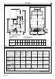
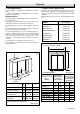
1 General B 9702 G L C E D A BOILER DRAIN POINT M K N DIMENSION BBU 54/4 J H F SIDE ELEVATION WATER CONNECTIONS RC1 FRONT ELEVATION GAS CONNECTION RC (1/2 in BSPT) A B C D E F G H J K L M N 338 244 124 97 545 348 390 195 195 38 146 175 173 Diagram 1.
1 General 1.5 Site Requirements 1.6 Water System - Open Vented Refer to diagram 1.1 for dimensions appropriate to the back boiler. This boiler can be used on an unrestricted open vented system with the water supply taken from a feed and expansion cistern, having a head between 1m (3ft 3in) minimum and 27m (90ft) maximum. For all types of installation a standard builder’s front opening is required, see diagram 1.2. Diagrammatic layouts of systems are shown in diagram 1.4 and 1.5.
1.7 Hot Water Cylinder 22mm VENT The back boiler is suitable for open vented systems using an indirect cylinder. The cylinder must be fitted to the manufacturer’s recommendations and the system must conform to the requirements of the current issue of BS5449. 9624 1 General 15mm COLD FEED INDIRECT CYLINDER It is recommended that the cylinder be fitted with some form of temperature control. 1m MIN. 27m MAX. 1.
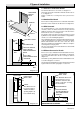
2 Types of Installation 5423 2.1 With Non-combustible Hearth For minimum dimensions of a hearth, see diagram 2.1. The back boiler must be installed level with the hearth or above it, see diagram 2.1. PREPARED BOILER BASE Carpet or similar floor covering must not be placed on the hearth. 2.2 Combustible Hearth 50mm MIN HEARTH If the hearth is existing and made of a combustible material the back boiler must be installed to the dimensions in diagram 2.3. 2.
3.1 General RIGID FLUE LINER The general recommendations of the current issue of BS5440 Part 1 should be followed. 1593 3 Flue and Ventilation In all cases the flue should be lined, preferably with a flexible liner. APPROVED SEAL FLEXIBLE LINER Where the installation is new it is essential to make sure that the annular space between the boiler flue liner and the chimney is sealed at the base and at the top of the chimney, as shown in diagram 3.2.
3 Flue and Ventilation 3.3 New Chimney VENT SIZES TABLE A newly built chimney can be lined with a moisture resistant lining, such as salt glazed pipe, of an appropriate diameter as specified in the Building Regulations 54/4 In the case of a salt glazed lined flue, it is recommended that a short vertical length of flue pipe, preferably flexible metallic be used. Fix and seal it to the back boiler flue socket, make good with approved packing and parge with fire cement, see diagram 3.1.
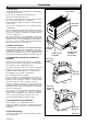
4.1 Preparation HEAT EXCHANGER Remove draught diverter body, draught diverter, flueway baffles and fittings pack from carton. Check contents of fittings pack against packed list. 9384 4 Installation Remove back boiler body from carton. Remove the combustion chamber extension by loosening the two securing screws and lift off, see diagram 4.1. Put the combustion chamber extension to one side until required, see note below.
4 Installation 9386 4.6 Chatsworth 4, Dovedale 4 Only IMPORTANT: With the control/burner assembly removed, fit the blanking plate, supplied with the fire front, to the rear of the combustion chamber and secure with a number 6 screw provided, see diagram 4.11. Please note that the hole for the securing screw in the blanking plate is offset to avoid incorrect fitting. HEAT EXCHANGER CASTING 4.7 Positioning the Back Boiler IMPORTANT.
4 Installation Chatsworth 4 and Dovedale 4 only and tighten, making sure the sensing tube is correctly positioned, see diagram 4.7. The back boiler must be positioned so that a line across the opening of the wall face coincides with the fire fixing wall face positioning line, see diagram 4.3. Where a flexible flue liner is being used, fully fit the No.8x3/8in self tapping screw provided into the rear of the flue socket as in diagram 4.8.
GAS SERVICE COCK (OFF) 9387 10260 4 Installation SENSING TUBE TUBING NUT SECURING SCREW COMBUSTION CHAMBER SCREW (4) SENSING TUBE SECURING BRACKET Fully fit No. 8 3/8 in. screw into rear of socket. Centralise flexible flue liner using the two No. 8 1/2 in. screws provided. Diagram 4.9 Diagram 4.6 REAR COMBUSTION CHAMBER No. 8 3/8 in. SCREWS BLANKING PLATE SOCKET 10112 LOCATING NIB GAS MANIFOLD SCREW FLUE BLOCKAGE SILICONE SAFETY DEVICE TUBE 9393 SENSING TUBE 9584 Diagram 4.8 FRONT No.
5 Electrical Wiring WARNING. This boiler must be earthed. Froststat Pipestat Double Pole Switchspur Programmer Roomstat ISOLATE THE ELECTRICAL SUPPLY BEFORE DOING ANY WIRING All of the electrical installation must be correctly earthed and be in accordance with the current issue of BS7671 and be carried out by a competent person. L Pump The boiler electrical supply is 230V~ 50Hz, fused at 3A. A double pole isolating switch, having a minimum contact separation of 3mm in both poles should be used.
5 Electrical Wiring Plug the short connecting lead (supplied in the fire front fittings pack) into the boiler user control L E N Refit the control box lid ensuring the boiler user control fits into the slot in the lid, see diagram 5.7. 9395 Slide the boiler user control into position on the control box front, making sure that it fits into the groove in the control box, and connect the lead plug on to P.C.B., see diagrams 5.8 and10.4.
9490 5 Electrical Wiring FLUE BLOCKAGE SAFETY DEVICE AND PILOT bk GAS VALVE wh g/y bk b br b b g/y or br br g/y bk bk THERMISTOR EARTH POST r b wh bk y g OVERHEAT CUT-OFF SAFETY DEVICE (SEALED SYSTEM ONLY) MAINS IN KEY Black Blue Brown Green Yellow Green/Yellow White Orange BOILER USER CONTROL bk b br g y g/y wh or Diagram 5.
6 Commissioning 6.1 Commissioning the Back Boiler continued - Before commissioning the back boiler, the whole of the system should be thoroughly flushed out with cold water with the circulation pump removed. Replace the pump, fill the system and examine for water soundness. Vent air from the system and pump. Make sure the thermistor phial is fitted correctly, see diagram 5.4. The back boiler unit is fitted with a flue blockage safety device, which will shut it down if there is a lack of oxygen.
6 Commissioning Technical Sequence of Operation Relight the back boiler by turning control thermostat knob "A" clockwise to maximum. When an external control calls for heat there is approximately a 5 second delay. The control board (PCB) energises the 1st gas valve solenoid, the valve will open and the spark unit will operate. With the valve open, gas is allowed to pass to the flue blockage safety device that will be ignited by the sparks.
6 Commissioning 6.2 Testing the Back Boiler Controls Make sure the back boiler control thermostat knob "A" is turned clockwise to maximum, which is about 82oC (180oC), against the setting point, allow the water to reach maximum working temperature. Examine the system for water soundness. To test the flame failure, turn the boiler on. After about 3 minutes, turn the gas service cock off, the lockout device should now operate. This is indicated by the red light coming on at the back boiler control panel.
7 Fire Installation Fire Front Installation and Servicing Instructions are packed with the fire. 7.1 Completion - After Installation of the Fire Front Instruct and demonstrate to the user, the efficient and safe operation of the boiler, heating and hot water system and fire front. Hand the Instructions for Use to the user, making sure that they are understood.
REMEMBER, When replacing a part on this appliance, use only spare parts that you can be assured conform to the safety and performance specification that we require. Do not use reconditioned or copy parts that have not been clearly authorised by Hepworth Heating Ltd. 9385 8 Servicing DRAUGHT DIVERTER BODY Servicing Notes a) To ensure the continued efficient and safe operation of the appliance it is recommended that it is checked and serviced as necessary at regular intervals.
8 Servicing 8.4 Controls Assembly and Burner. Disconnect the union at the gas service cock, see diagram 8.2. Disconnect the mains electrical plug from the control box, see diagram 8.2. Remove the thermistor phial from the phial pocket taking care not to damage the cable, see diagram 5.4. Remove the four combustion chamber securing screws. Remove the gas manifold securing screw and slide the control/ burner assembly forwards to remove, see diagram 8.2. 8.
8 Servicing 9607 8.7 Main Burner - Injector Inspect the main burner injector for damage or blockage, clean or replace as necessary, see diagram 8.5. GAS CONTROL VALVE MAIN BURNER INJECTOR Diagram 8.5 SPARK GAP 3 +1 or -0.5 EARTH POST 9520 SECURING SCREWS GAS MANIFOLD PILOT TUBE NUT 9587 Do not use a wire or sharp instrument to clean the injector hole. SENSOR 13mm ELECTRODE SENSING LEAD Diagram 8.6 IGNITION LEAD 9595 LINT ARRESTER 9593 Diagram 8.
8.8 Flue Blockage Safety Device Assembly Firelite 4, Contour 4, Miami 4, Heartbeat 4 and Black Beauty 4 only BAFFLES Gain access as relevant part of Section 8.4. Remove any dust and lint, inspect the pilot for damage. Remove the sensing tube adapter, to clean, blow through, do not use a wire or sharp instrument. If necessary replace the flue blockage safety device. 9597 8 Servicing BACK FLUEWAY Check for the correct spark gap, see diagram 8.6.
9 Fault Finding 9.1 Electrical NOTE. If the electrical supply is switched rapidly off and on without gas present the control will purge for 100 sec. Neither of the indicators will be lit. The appliance will then operate correctly. Is there 230v ac across Blue and Brown at (Connector X1) 9605 Carry out the preliminary electrical system checks as contained in a multimeter instruction book.
9 Fault Finding Refer to electrical fault finding chart, diagram 9.1 and functional flow wiring diagram 9.2. 9.2 Electrical Fault Finding Back Boiler Refer to diagram 9.1. On completion of the fault finding task which has required the breaking and remaking of electrical connections, the checks for earth continuity, short circuit, polarity and resistance to earth must be repeated. 9.
10 Replacement of Parts IMPORTANT. When replacing the heat exchanger please remember that it exceeds the recommended weight for a one man lift, refer the Manual Handling Operations, 1992 Regulations for further information. 10.3 Electrode Proceed as in Section 10.2. 10.4 Ignition Lead and Sensing Lead Notes. Remove the control box lid, see diagram 10.3. a) Replacement of parts must be carried out by a competent person. Remove the lead from the electrode or sensor, see diagram 10.4.
10.6 Gas Valve GAS CONTROL VALVE BOARD ELECTRICAL PLUG (PCB) SENSING PLUG IGNITION LEAD LEAD SECURING SCREW Refer to the relevant parts of Section 8.4 to remove the controls assembly. Refer to diagram 10.2. Remove securing screw and disconnect electrical plug, see diagram 10.2. Disconnect the pilot tubing nut at the gas valve. 9603 10 Replacement of Parts Undo the securing screws to separate the valve from the supply pipe flange and gas manifold.
10 Replacement of Parts 10165 10.10 Overheat Cut-off Safety Device (Sealed systems only) Unclip the overheat cut-off safety device from the flow pipe, it is located near where the flow pipe exits from the heat exchanger. Withdraw the retaining clip with the overheat cut-off safety device from the lead plug. Remove overheat cut-off safety device from clip and discard. Fit new overheat cut-off safety device in clip and re-locate in the lead plug, making sure that the terminals fully engage in the plug.
11 Spare Parts When spare parts are required apply to your local supplier. Please quote the name of the appliance, also the serial number of the boiler, to be found on the data label on the appliance. If ordering from the local gas undertaking the appropriate appliance GC number should also be quoted together with the GC number of the part. Key No. Part No.
2000225024C
Because of our constant endeavour for improvement, details may vary slightly from those shown in these instructions.