
User guide

26
221724B
10 Replacement of Parts
6853
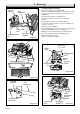
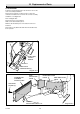
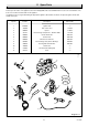
Diagram 10.5
SECURING
SCREW (5)
COMBUSTION
CHAMBER
FRONT COVER
SIDE
INSULATION
PIECE
REAR INSULATION
PIECE
SIDE INSULATION
PIECE
FRONT
INSULATION PIECE
7158
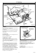
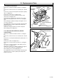
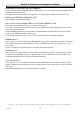
Diagram 10.4
ELECTRICAL
CONNECTIONS (2)
OVER HEAT
CUTOFF
DEVICE
LOCKNUT
CAPILLARY
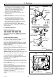
10.12 Insulation
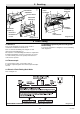
Follow the relevant instructions in Section 8.3 to remove the
controls assembly and burner.
Remove the five burner securing screws to remove the
combustion chamber front cover from the controls assembly
and burner, see diagram 8.2.
Refer to diagram 10.5
Remove the front cover insulation,
Slide out the side insulation pieces.
With the side insulation pieces removed, lift out the rear
insulation.
Note: Remove any debris that falls when the insulation has
been replaced.