
User guide

12
221724B
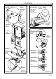
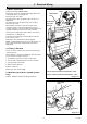
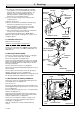
Diagram 4.9
6847
DRAUGHT
DIVERTER
ASSEMBLY
SECURING
SCREW (2)
Pipework removed for clarity
Diagram 4.8
6177
BAFFLES
HEAT EXCHANGER
BACK
FLUEWAY
Pipework removed for clarity
SECURING
SCREW (2)
SPIGOT
DUCT
MIDDLE
FLUEWAY
4 Installation
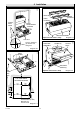
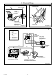
Diagram 4.6
6872
CUT-OUT
FIXING
WALL
FACE
Diagram 4.7
6875
FIXING
HOLE
(5 OFF)
FIRE
FIXING
WALL
FACE
FIXING HOLE (5 OFF)
Minimum of 2
must be used
HEAT
EXCHANGER
CASTING
Line the appliance
up with the wall
fixing face
TOP VIEW INSIDE
BUILDERS OPENING