221724B.10.00 Installation & Servicing Instructions To b e l e f t w i t h t h e u s e r Glow-worm 56/3pp Back Boiler Unit G.C. No. 44 047 03A 6824 This Back Boiler Unit Is To Be Used Only With The Glow-worm Mk.3 Fire Front Range This is a Cat I2H Appliance Customer Services: Tel: (01773) 828100 One Contact Local Service Fax: (01773) 828070 Hepworth Heating Ltd., Nottingham Road, Belper, Derbyshire.
1 General 1.2 Data The instructions consist of three parts, Installation and Servicing Instructions for the Back Boiler Unit, Installation and Servicing Instructions for the Fire Front and Instructions for Use, which includes the Guarantee Registration Card. The instructions are an integral part of the appliance and must, to comply with the current issue of the Gas Safety (Installation and Use) Regulations, be handed to the user on completion of the installation.
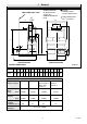
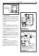
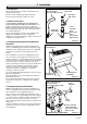
FIRE FIXING WALL FACE CL FLUE E WATER CONNECTIONS 22mm COPPER PIPE INSIDE DIAMETER OF SOCKET FOR 125mm (5in) NOMINAL DIAMETER FLUE GAS CONNECTION RC (1/2 in BSPT) B R H N CL of Flue F 6837 1 General S T A P D G L K C J J FRONT ELEVATION M SIDE ELEVATION Diagram 1.
1 General 1.6 Water System - Open Vented 1.12 Back Boiler Location This back boiler can be used on an unrestricted open vented system with the water supply taken from a feed and expansion cistern, having a head between 1m (3ft3in) minimum and 27m (90ft) maximum. This back boiler MUST NOT be installed in a private garage or in a room containing a bath or shower or in a room used or intended to be used as sleeping accommodation. Diagrammatic layouts of systems are shown in diagram 1.4 and 1.5.
6408 1 General * CORNER IN-FILL (not required to be full depth of opening) FRONT OPENING 6242 405 mm. MIN. Diagram 1.3 1.13 BSI Certification 28mm IMPORTANT DIMENSION NOT LESS THAN 145mm Any alteration that is not approved by Hepworth Heating Ltd., could invalidate the BSI Certification of the boiler, warranty and could infringe the current issue of the Statutory Requirements.
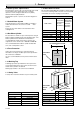
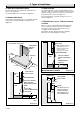
2 Types of Installation 2.1 With Non-combustible Hearth 2.3 With Surround The back boiler must be installed level with the hearth or above it, see diagram 2.1. The combined thickness of the surround and lintel must be checked, to make sure that the back boiler can be positioned within the opening to allow easy connection of the flue into the back boiler flue socket, see diagram 2.3. For minimum dimensions of a hearth see diagram 2.1.
3.1 General The general recommendations of the current issue of BS5440 Part 1 should be followed. SEALING AND CLAMPING PLATE In all cases the flue should be lined, preferably with a flexible liner. It is essential that the flue has an equivalent height of at least 2.5m (8.2ft) measured from the flue connection on the appliance. The first 600mm, at least, above the draught diverter must be vertical. 6197 3 Flue and Ventilation AIR SPACE The flue socket is designed to take flue pipe to BS567.
3 Flue and Ventilation If a flue and false chimney breast are to be constructed all openings for pipework to upper floors etc., must be sealed. The only opening for the back boiler must be at the front, being of the dimensions as shown in diagram 1.2. If a specially built compartment is constructed for the back boiler, it must conform to the requirements of the current issue of BS5440 Part 1 and BS5871. The flue should, preferably, end above ridge height but at least above the eaves of a pitched roof.
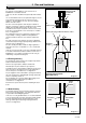
4.1 Preparation 22mm COPPER PIPE SUPPLIED WITH APPLIANCE (Do not cut) Remove draught diverter assembly, flueway baffles and fittings pack from carton. 6254 4 Installation INJECTOR Check contents of fittings pack against packed list. UNEQUAL TEE PIECE Remove back boiler body assembly from carton. 4.2 Water Connections IT IS EXTREMELY IMPORTANT THAT NO SERVICE PIPES ARE ROUTED IN FRONT OF THE BOILER.
4 Installation 6842 FITTING THE INJECTOR 22mm COPPER PIPE SUPPLIED WITH APPLIANCE (Do not cut) 22mm CENTRAL HEATING RETURN INJECTOR (Supplied) 28mm UNEQUAL TEE (supplied) 22mm 145 mm MINIMUM 28mm DOMESTIC HOT WATER FLOW 22mm COPPER PIPE SUPPLIED WITH APPLIANCE (Do not cut) 6841 22mm COPPER PIPE SUPPLIED WITH APPLIANCE (Do not cut) 22mm CENTRAL HEATING RETURN 22mm CENTRAL HEATING FLOW (Must run down to allow air in system to escape) METHOD A 28mm DOMESTIC HOT WATER FLOW (Must rise to allow air
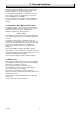
4.5 Heat Shield Assembly SECURING SCREW (2) Slacken, Do not remove If the boiler electrical supply cable has to be routed down the left hand side of the combustion chamber you must fit the heat shield assembly and clips supplied in the fittings pack. Refer to Section 5.1 and diagrams 5.2 and 5.3. 6870 4 Installation COMBUSTION CHAMBER EXTENSION 4.6 Circulating Pump Isolating valves, integral if possible, must be fitted each side of the circulating pump. 4.
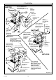
6872 6177 4 Installation BAFFLES MIDDLE FLUEWAY BACK FLUEWAY FIXING WALL FACE HEAT EXCHANGER CASTING HEAT EXCHANGER Pipework removed for clarity Diagram 4.8 DRAUGHT DIVERTER ASSEMBLY Line the appliance up with the wall fixing face SECURING SCREW (2) SPIGOT DUCT 6847 CUT-OUT FIXING HOLE (5 OFF) 6875 Diagram 4.6 SECURING SCREW (2) FIRE FIXING WALL FACE Pipework removed for clarity TOP VIEW INSIDE BUILDERS OPENING FIXING HOLE (5 OFF) Minimum of 2 must be used Diagram 4.
4 Installation 6848 REAR Fully fit No. 8 3/8 in. screw into rear of No. 8 3/ 8 in. socket. Centralise SCREW flexible flue liner using the two No. 8 1/2 in. SOCKET screws provided. SENSING TUBE BRACKET SECURING SCREW 6849 DRAUGHT DIVERTER FRONT No. 8 1/2 in. SCREWS (BLACK) SENSING TUBE (push fit) 6873 Diagram 4.
5 Electrical Wiring 5.1 General If right hand access is required fit the three clips from the fittings pack to the combustion chamber extension and route the cable down the right hand side of the combustion chamber. Keep the cable well clear of hot surfaces, see diagram 5.3. WARNING. This boiler must be earthed.
5.3 Boiler Control Box CONTROL THERMOSTAT PHIAL Taking care that the POWER IS OFF. Remove the control box, hold with both hands squeeze tilt forward and unhook, see diagram 5.5. RETAINING PIN Remove the gas valve lead. Thread the mains cable through the side of the box, see diagram 5.6. 6879 5 Electrical Wiring C OVERHEAT CUT-OFF DEVICE The mains cable outer insulation must not be cut back external to the clamp.
CABLE CLAMP 7092 CONTROL BOX 7155 5 Electrical Wiring CONTROL BOX 3 WAY TERMINAL BLOCK N SLOT Ls SWITCHED CONTROLLED MAINS SUPPLY 230V~50Hz Diagram 5.6 Diagram 5.7 7883 KEY br b g/y r N Lp Ls - CAPILLARY brown blue green/yellow red neutral permanent live switched live b r N Ls g/y b 3WAY TERMINAL BLOCK 230V~50Hz SWITCHED CONTROLLED SUPPLY CHASSIS EARTH g/y br br r r GAS CONTROL VALVE CONTROL THERMOSTAT OVERHEAT CUT-OFF (SEALED SYSTEMS ONLY) Diagram 5.
6 Commissioning Set the thermostat control knob “A” to “Off” that is, fully anticlockwise. 6.1 Commissioning the Back Boiler Before commissioning the back boiler, the whole of the system should be thoroughly flushed out with cold water with the circulation pump removed. Replace the pump, fill the system and examine for water soundness. Vent air from the system and pump. Make sure the thermostat phial is fitted correctly, see diagram 5.4.
6 Commissioning If the boiler is used with a Miami 3 or Melody 3 fire front it is permitted to increase the output to 16.4 kW (56000) Btu/h). There should be no undue noise in the pipework or heat emitters. There must be NO pumping over of water or entry of air at the open vent pipe above the feed and expansion cistern. If adjustment is required, TEN MINUTES after lighting, remove cover “G” and turn adjustment screw, anti-clockwise to suit system design heat input.
7 Fire Installation 7.1 Completion - After Installation of the Fire Front Instruct and demonstrate to the user, the efficient and safe operation of the boiler, heating and hot water system and fire front. Hand the Instructions for Use to the user, making sure that they are understood. Advise the user that to ensure the continued efficient and safe operation of the appliance it is recommended that it is checked and serviced as necessary at regular intervals.
Servicing Notes SENSING TUBE RETAINING FITTING NUT INTERNAL FILTER a) To ensure the continued efficient and safe operation of the appliance it is recommended that it is checked and serviced as necessary at regular intervals. The frequency of the servicing will depend upon the particular installation conditions and usage, but in general once a year should be enough. b) It is the Law that servicing must be carried out by a competent person.
7093 8 Servicing COMBUSTION CHAMBER COMBUSTION SECURING SCREWS (2) CHAMBER BURNER SECURING SCREWS (3) GAS MANIFOLD SECURING SCREW (2) UNION NUT GAS SERVICE COCK COMBUSTION CHAMBER FRONT COVER CONTROL BOX 8.4 Burner GAS CONTROL VALVE SECURING BRACKET Disconnect the pilot tube nut and the thermocouple nut from the gas control valve, see diagram 8.5. Remove the screws which locate the gas manifold to burner, see diagram 8.5. Diagram 8.
8 Servicing 8.10 Back Boiler Flueways 6905 GAS CONTROL VALVE GAS MANIFOLD Remove the spigot duct, see diagram 8.10. Remove the draught diverter plate by slackening the two side securing screws and removing the rear securing screw, see diagram 8.10. Lift out the flueway baffles, see diagram 8.11. Place a sheet of paper in the base of the combustion chamber. Clean the boiler flueways with a suitable stiff brush. To make sure that the flueways are clean, view with the aid of a mirror or reflector.
6835 DRAUGHT DIVERTER ASSEMBLY FLUEWAY BAFFLES BACK FLUEWAY 7195 8 Servicing SPIGOT DUCT SECURING SCREW (3) MIDDLE FLUEWAY SECURING SCREW (2) DRAUGHT DIVERTER PLATE HEAT EXCHANGER Diagram 8.11 Diagram 8.10 9 Fault Finding 9.1 Electrical 9.4 Flue Blockage Safety Device and Ignition Fault Finding Carry out the preliminary electrical system checks as contained in a multimeter instruction book. To check the safety device and ignition, refer to fault finding chart, diagram 9.1.
10 Replacement of Parts Notes. 10.7 Injector - Main Burner a) Replacement of parts must be carried out by a competent person. Follow the instructions in Section 8.4 to remove the burner. Replace the main injector. Ensure you fit the new copper washer, see diagram 8.7. b) Unless stated otherwise all parts are replaced in the reverse order to that of removal. c) After replacing any gas carrying parts always test for gas soundness using a suitable leak detection fluid.
10.10 Control Thermostat Remove the combustion chamber extension, see diagram 4.5. SECURING SCREWS (4) Remove the control box refer to the relevant parts of Section 8.3. GAS CONTROL VALVE UNION NUT GAS SERVICE COCK 7094 10 Replacement of Parts Remove the control thermostat phial and unclip the capillary tube, see diagram 5.4. Remove the control knob, see diagram 10.3. Remove the two electrical connections from the control thermostat, see diagram 10.3.
10 Replacement of Parts 10.12 Insulation Follow the relevant instructions in Section 8.3 to remove the controls assembly and burner. Remove the five burner securing screws to remove the combustion chamber front cover from the controls assembly and burner, see diagram 8.2. Refer to diagram 10.5 Remove the front cover insulation, Slide out the side insulation pieces. With the side insulation pieces removed, lift out the rear insulation.
11 Spare Parts When spare parts are required apply to your local supplier. Please quote the name of the appliance, Glow-worm 56/3pp BBU, with a relevant BBU Fire Front, also the serial number of the boiler, to be found on the data label on the appliance. If ordering from the local gas undertaking the appropriate appliance GC number should also be quoted together with the GC number of the part. Part No. Description GC Part No.
Control of Substances Hazardous to Health Information for the Installer and Service Engineer. Under Section 6 of The Health and Safety at Work Act 1974, we are required to provide information on substances hazardous to health. The adhesives and sealants used in this appliance are cured and give no known hazard in this state. RADIANTS, FUELBEDS, ARTIFICIAL FUEL After handling wash hands thoroughly.