221781A.07.00 Installation and Servicing Instructions To be left with the user Glow-worm 56/2 Back Boiler Unit GC No 44 315 40 8010 For use with specially designed Glow-worm fire fronts only References in these instructions to British Standards and Statutory Regulations/Requirements apply only to the United Kingdom. For Ireland the rules in force must be used.
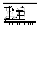
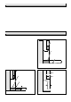
6070 1 General CL CL FLUE FLUE GAS CONNECTION Rc 1/2 (1/2 in. BSPT) M C WATER CONNECTION Rc1 (1in. BSPT) ON RIGHT-HAND SIDE OR LEFT-HAND SIDE (R.H. SHOWN) L N F Q A INSIDE DIAMETER OF SOCKET FOR 125mm (5in) NOMINAL DIAMETER FLUE H J K B Dimension A B C '56/2' BACK BOILER 547 357 146 GENERAL DIMENSIONS All dimensions are in millemetres G D E P Diagram 1.
1 General 1.3 Gas Supply RANGE RATING TABLE The gas installation shall be in accordance with the current issue of BS6891. RANGE RATING NOMINAL kW HEAT INPUT (GROSS) Btu/h NOMINAL kW HEAT Btu/h OUTPUT BURNER mbar SETTING PRESSURE in.w.g The supply from the governed meter must be of adequate size to provide a steady inlet working pressure of 20mbar (8in wg) at the back boiler.
1 General 1.8 Hot Water Cylinder 1.13 BSI Certification The back boiler is suitable for open vented systems using an indirect cylinder (including single feed self priming type). The indirect cylinder must be fitted to the manufacturer’s recommendations and the system must conform to the requirements of the current issue of BS5546 and BS6700. This appliance is certificated to the current issue of BS6332 Part 1 invoking the current issue of BS5258 Part 8 for safety and performance.
1 General CE Mark 1.14 Inhibitor The CE mark on this appliance shows compliance with: Attention is drawn to the current issue of BS5499 and BS7593 on the use of inhibitors in central heating systems. 1. Directive 90/396/EEC on the approximation of the Laws of the Member States relating to appliances burning gaseous fuels. If an inhibitor is to be used, contact a manufacturer for their recommendations as to the best product to use.
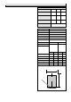
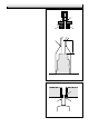
3 Flue and Ventilation 1592 3.1 General The general recommendations of the current issue of BS5440 Part 1 should be followed. SEALING AND CLAMPING PLATE In all cases the flue should be lined, preferably with a flexible liner. It is essential that the flue has an equivalent height of at least 2.5m (8.2ft) measured from the flue connection on the appliance. The first 600mm, at least, above the draught diverter must be vertical. AIR SPACE The flue socket is designed to take flue pipe to BS567.
3 Flue and Ventilation 3.4 Ventilation - Back Boiler and Fire Front 3.5 Extract Fans It is important that the room in which the back boiler unit is installed has adequate air inlets to ensure correct operation as specified in the current issue of BS5440 Part 2. If an extract fan is fitted in the premises, there is a possibility that if adequate air inlet openings are not provided spillage of the products of combustion could occur.
4 Installation Mark through the fixing holes each side of the combustion chamber, see diagram 4.4. Remove the back boiler. Drill two holes to accept the plugs and fixings provided. 4.4 Pumped Heating and Hot Water The pumped flow connection must be diametrically opposite to the pumped return connection. If access to the fixing holes shown in diagram 4.4 is difficult, use the alternative method described in Section 4.8 otherwise proceed as Section 4.9. Refer to diagram 1.4 for a diagrammatic layout.
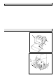
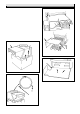
4.9 Positioning the Back Boiler - continued 8015 4 Installation SECURING SCREWS Fit the flue baffle on top of the heat exchanger ensuring that the four corners are correctly located into the flueways, see diagram 4.5. The flue baffle is marked “TOP FRONT”. Fit the draught diverter onto the heat exchanger with the four screws provided in the fittings pack, see diagram 4.6. taking care not to damage the seal.
5.1 General THERMOSTAT CAPILLARY WARNING. This boiler must be earthed. ISOLATE THE ELECTRICAL SUPPLY BEFORE DOING ANY WIRING. CAPILLARY CLIPS TO R.H. PHIAL POCKET MAINS CABLE All of the electrical installation must be correctly earthed and be in accordance with the current issue of BS7671 and be carried out by a competent person. 8011 5 Electrical Wiring The mains supply required is 230V~ 50Hz, fused at 3A.
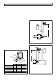
8082 5 Electrical Wiring BLACK BLUE N L N Ls E VIEW OF PLUG WHEN REMOVED GREEN/YELLOW GREEN/ YELLOW BLACK BROWN GAS VALVE C L N E NC 230V ~ 50Hz MAINS SUPPLY FUSED AT 3 AMP THERMOSTAT Diagram 5.4 Checks to ensure electrical safety must be carried out by a competent person. 8021 5.4 Testing - Electrical CONTROL BOX After installation of the system, preliminary electrical system checks as below should be carried out, 1. Test insulation resistance to earth of mains cable. 2.
6 Commissioning 6.1 Commissioning the Back Boiler Remove the back boiler burner pressure test screw “G” and connect a suitable pressure gauge. The Back Boiler is fitted with a flue blockage safety device which will shut it down if there is a lack of oxygen. If flue blockage safety device sensing tube is not fitted, remove the plastic ferrule from the bulkhead connector on the air duct, replace ferrule after testing/commissioning.
6 Commissioning 3924 S Should any doubt exist, the gas rate should be checked at the gas meter. The rate of the back boiler should be within the range, 1.64 m/3h to 2.15 m3/h GAS SERVICE COCK UNION 58.0 ft3/h to 76.0 ft3/h Note, if the gas rate is checked, make sure that all other gas appliances and pilot lights are turned off. Turn control thermostat knob “B” anti-clockwise to “O” “Off” position. Remove pressure gauge and replace test point screw make sure that a gas tight seal is made.
6.4 Commissioning the System 20mm Set all controls to operate the heating system. Adjust pump and balance the system to give a temperature drop across the boiler of 11oC (20oF). At the appropriate flow rate, the resistance of the back boiler can be found by reference to diagram 6.4. FLAME DIMENSION 5197 6 Commissioning Pilot Shield omitted for clarity There should be no undue noise in the pipework or heat emitters.
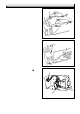
8 Servicing 1613 8.1 Servicing Notes. (a) To ensure the continued efficient and safe operation of the appliance it is recommended that it is checked and serviced as necessary at regular intervals. SECURING SCREWS The frequency of the servicing will depend upon the particular installation conditions and usage, but in general once a year should be enough. (b) It is the Law that servicing must be carried out by a competent person. BURNER (c) Remove the fire front.
Undo the two nuts shown in diagram 8.5 which secure the main gas manifold to the burner and remove the shakeproof washers, disengage the lint arrester and then withdraw the main gas manifold from the burner. 5199 8 Servicing EARTH POST SPARK GAP +1 3 -0.5 Clean the lint arrester as necessary. Inspect the main burner injector for damage or blockage, clean or replace as necessary using a small amount of approved jointing compound, on the external thread.
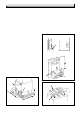
GUIDE CHANNELS SECURING SCREW (2) STAINLESS STEEL SECURING SCREWS(2) 1620 5079 8 Servicing DIVERTER PLATE FLUE BAFFLE FLUE COLLECTOR ASSEMBLY 1621 Diagram 8.8 Diagram 8.6 5201 FIRE FRONT SENSING TUBE FLUE BAFFLE SECURING SCREW FLUEWAYS Diagram 8.9 Diagram 8.7 8033 9 Replacement of Parts 9.1 Notes on Replacing Parts. (a) Replacement of parts must be carried out by a competent person.
9.2 Flue Blockage Safety Device Assembly NOTE: It is important that the thermostat is fitted the same way as shown in diagram Gain access as the relevant part of Section 8.3. Remove lead from electrode. ELECTRICAL CONNECTIONS Pull off back boiler lower sensing tube. Undo the pilot tube securing nuts and the thermocouple nuts at gas valve, see diagram 8.4.
9 Replacement of Parts 9.8 Control Thermostat 9.9 Viewing Window Disconnect the gas valve electrical plug, see diagram 5.2. Gain access as the relevant parts of Section 8.3. Remove the split pin to release the control thermostat phial, see diagram 5.6. Remove the old self adhesive aluminium foil gasket and the old mica window. Replace with a new mica window. Peel off the backing paper and secure with new self adhesive aluminium foil gasket, see diagram 9.3.
Isolate Isolate power power supply supply to to the the control control box. box. Gain Gain access access to to the the control control box box and and physically physically check check all all wires wires and and connections. Check fuses.Check Flue Blockage Safety Device filter is not blocked, clear if necessary. connections. Check fuses. Check that all remote controls, (eg room and / or cylinder thermostats), are making contact for duty.
6131 10 Fault Finding Disconnect appliance thermocouple from the gas valve. Check that all connections are clean and in good condition. Fit test meter interrupter into the magnet unit. Fit appliance thermocouple into the test meter interrupter. Check that the flue blockage safety device sensing filter is clean, if not remove / clean and replace. Hold down control knob on gas valve. Ignite pilot burner and allow thermocouple to attain operating temperature. Measure the OPEN CIRCUIT voltage.
5278 10 Fault Finding PILOT WILL NOT LIGHT START HERE Check gas line-open all cocks, rectify any blockages, purge out any air. Does pilot light? NO Does pilot stay alight when gas valve knob is released? NO YES Apply match to pilot burner instead of pressing piezo unit button. Does pilot light? NO PILOT SATISFACTORY YES Undo tubing nut at pilot burner. Press gas valve knob.
11 Spare Parts When spare parts are required apply to your local supplier. Please quote the name of the appliance, Glow-worm 56/2 BBU, also the serial number of the back boiler, to be found on the data label on the combustion chamber extension, see diagram 6.1. 8034 If ordering from British Gas the GC number should also be quoted, together with the GC number of the part. 2 3 8 6 9 5 1 10 4 7 Diagram 11.1 Key No Part No.
Control of Substances Hazardous to Health Information for the Installer and Service Engineer. Under Section 6 of The Health and Safety at Work Act 1974, we are required to provide information on substances hazardous to health. The adhesives and sealants used in this appliance are cured and give no known hazard in this state. INSULATION PADS/CERAMIC FIBRE, GLASSYARN These can cause irritation to skin, eyes and the respiratory tract.