0020013349-02.06.05 Instructions for Use Installation and Servicing To b e l e f t w i t h t h e u s e r 12175 24cxi G.C. No. 47-047-23 30cxi G.C. No. 47-047-24 38cxi G.C. No. 47-047-27 High Efficiency Condensing Combination Boilers Glow-worm, Nottingham Road, Belper, Derbyshire. DE56 1JT www.glow-worm.co.
Guarantee Registration Thank you for installing a new Glow-worm appliance in your home. Glow-worm appliances are manufactured to the very highest standard so we are pleased to offer our customers a Comprehensive Guarantee. This product is guaranteed for 24 months from the date of installation or 30 months from the date of manufacture, whichever is the shorter, for parts.
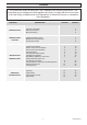
Contents The instructions consist of three parts, User, Installation and Servicing Instructions. The instructions are an integral part of the appliance and must, to comply with the current issue of the Gas Safety (Installation and Use) Regulations, be handed to the user on completion of the installation. CONTENTS INTRODUCTION INSTRUCTIONS FOR USE INSTALLATION INSTRUCTIONS SERVICING INSTRUCTIONS DESCRIPTION SECTION PAGE No.
Important Information WARNINGS Gas Leak or Fault Turn off the gas emergency control valve immediately. Eliminate all sources of ignition, i.e.smoking, blowlamps, hot air guns etc. Do not operate electrical lights or switches either on or off. Open all doors and windows,ventilate the area. Sheet Metal Parts This boiler contains metal parts (components) and care should be taken when handling and cleaning, with particular regard to edges.
General Information General Note Condensate Drain This boiler is designed for use as part of a sealed water central heating system with fully pumped circulation. The pump, expansion vessel and associated safety devices are all fitted within the boiler. The condensate drain, see section 8.2, must not be modified or blocked. Once the controls are set the boiler operates automatically. Like all condensing boilers this appliance will produce a plume of condensation from the flue terminal in cool weather.
Manual Handling Carriage of carton from point of delivery to point of installation – first or higher floor, cellar. Positioning of Appliance for Final Installation – above worktop, foreseeable obstructions etc. Recommend 2-person lift or 1 person with use of sack truck. If 1 person is performing lift, straddle the load, tilt and place carton into position on truck. Recommend secure appliance onto truck with suitable straps. Ensure safe lifting techniques are used – keep back straight – bend using legs.
Appliance Safety Devices - User Instructions Electrical Supply Failure Reset Switch Frost protection The boiler will not work without an electrical supply. The appliance has a built in frost protection device that protects the boiler from freezing. With the gas and electric supplies ON and irrespective of any room thermostat setting, the frost protection device will operate the pump when the temperature of the boiler water falls below 7OC.
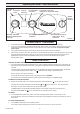
CONTROLS CONTROL FASCIA LIGHT DIGITAL DISPLAY NO PRE-HEAT POSITION 9934 Operating the Boiler - User Instructions ECONOMY POSITION APPROX 55O WITH PRE-HEAT MAINS RESET SWITCH CENTRAL HEATING WATER TEMPERATURE CONTROL HOT WATER TEMPERATURE CONTROL MAXIMUM POSITION APPROX 62O WITH PRE-HEAT Diagram 1 OPERATION OF THE BOILER 1. Check that all isolating valves on the boiler are open and that water flows from the hot water tap. 2.
Operating the Boiler - User Instructions 12945 Digital Display/ System Pressurisation The digital display normally shows the operating temperature of the unit when there is a central heating demand and gives a pressure reading when there is no demand or when the appliance is in the domestic hot water mode. If the digital display shows pressure less than 0.7bar, repressurise the system to 1bar by gently opening the built in filling tap underneath the boiler, see diagram 2.
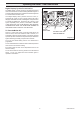
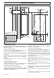
12891 1 Technical Information 334 87 176 14 FLUE CENTRE LINE CL FLUE 76 CL BOILER 715 SAFETY DISCHARGE DRAIN 117 THIS DIMENSION CAN BE INCREASED TO 600mm MAX. 22 18 44 77 GAS 21 86 156 134 450 GENERAL ARRANGEMENT Diagram 1.1 1.1 IMPORTANT NOTICE The Water Fittings Regulations or Water byelaws in Scotland. The boiler is supplied in one carton, which includes a fittings pack, pipe pack, fixing jig, condense pipe, and documentation pack, see diagram 6.1 and 6.1a.
1 Technical Information 12923 TABLE 1 Lift Weight Total Weight (installed) 24cxi 41kg(90lb) 44kg(97lb) 30cxi 38cxi 42kg(92.5lb) 44kg(97lb) 45kg(99lb) 47kg(103.5lb) ● Gas connection 22mm copper ● Heating and return 22mm copper ● Domestic hot water 15mm copper Safety valve Preset 3bar (43.5lbf/in2) Safety valve discharge 15mm copper ■ Expansion vessel capacity Charge pressure 8 litres (1.76 gallons) 0.5bar (7.3lbf/in2) 0.7bar (10.1lbf/in2) Heating system minimum pressure D.H.W Max.
1 Technical Information 9165 Certification This boiler certificated to the current issue of EN 483 : 2000 for performance and safety. It is important that no alteration is made to the boiler, without permission, in writing, from Glow-worm. Any alteration that is not approved by Glow-worm, could invalidate the warranty and could also infringe the current issue of the Statutory Requirements. 1.3 Gas Supply The gas installation must be in accordance with the relevant standards. In GB this is BS6891.
2 Boiler Location and Ventilation 12344 2.1 Location This boiler is not suitable for outdoor installation. This boiler may be installed in any room, although particular attention is drawn to the installation of a boiler in a room containing a bath or shower where reference must be made to the relevant requirements. 5 5 This boiler is suitable for installation in bathroom zones 2 and 3. In GB this is the current I.E.E. WIRING REGULATIONS and BUILDING REGULATIONS.
3 Flue Location and Ventilation 3.1 Flue Options 3.2 Flue Length This boiler is suitable for concentric Horizontal and Vertical flues, elevated horizontal and vertical twin, all are fitted onto the top of the boiler. The maximum permissable horizontal flue length is 10 metres plus the flue terminal, this can be achieved by use of the accessories, however should additional 90o or 2 x 45o elbows be used then the length MUST be reduced by 1metre.
3 Flue Location and Ventilation 3.4 Terminal Position The minimum acceptable siting dimensions for the terminal from obstructions, other terminals and ventilation openings are shown in diagram 3.5. For Ireland the minimum distances for flue terminal positioning must be those detailed in I.S.813 "Domestic Gas Installations". The terminal must be exposed to the external air, allowing free passage of air across it at all times. Being a condensing boiler some pluming may occur from the flue outlet.
4 Heating System 4.1 General 4.3 Flow Rate The boiler is for use only with sealed central heating systems. If it is necessary to alter the flow rate, the system can be fitted with a lockable balancing valve in the main flow or return pipes shown as valve "A" in diagram 4.1. The flow rate through the boiler must not be allowed to fall below that given in table 3. The safety valve is an integral part of the boiler and it cannot be adjusted.
4 Heating System 4.6 Water Treatment In the case of an existing installation, it is ESSENTIAL that prior to installing the new boiler the system is thoroughly flushed. For optimum performance after installation of a new system, the boiler and its associated central heating system should also be flushed. Flushing should be carried out in accordance with BS7593: 1992 using a cleanser such as Sentinel X300 or X400, Fernox restorer or Salamander corrosion guard cleaner.
5 Domestic Hot Water System water pipework. However, in areas where the water is 'hard' (i.e. more than 200mg/litre), it is recommended that the hot water setting is reduced and that a scale reducer is fitted. 5.1 Water Pressure The maximum working pressure of the domestic hot water circuit is 10 bar. If the cold water supply pressure exceeds this, then a pressure-reducing valve must be fitted in the supply to the boiler.
12912 6 Installation Preparation SEALING WASHER 12x18x2 1 off SEALING WASHER 18x23x1.5 4 off SEALING WASHER 14x18x1.5 5 off SEALING WASHER 16x24x1.5 9 off FLOW RESTRICTOR 1off FITTINGS PACK HEATING FLOW CONNECTION HEATING FLOW PIPE D.H.W OUTLET PIPE GAS SUPPLY PIPE COLD WATER INLET PIPE D.H.W CONNECTION SAFETY DISCHARGE VALVE PIPE HEATING RETURN PIPE GAS CONNECTION PIPE HEATING RETURN CONNECTION D.H.
6.2 Wall Template Take the wall template from the documentation pack and place in the desired position on a flat wall, giving due consideration to boiler clearances, see section 2, and the flue you are fitting. 2.5° 44mm/metre Inclined Extended flue length WALL TEMPLATE 176 6.3 Flue Hole Cutting The standard horizontal flue is designed with an internal fall of 44mm/metre towards the boiler for disposal of condensate.
7 Gas/Water & Appliance Connection 7.1 System Connection 7.3 Water Connections The system can now be connected without the boiler being mounted. All water and gas connections are on the fixing jig with the exception of the condense drain and safety discharge, the positions of these are shown on the wall template. Flush out the domestic hot water and the heating systems before connecting to the boiler.
8 Safety Discharge Valve and Condensate Connections 11694 8.1 Safety Discharge Valve SAFETY DISCHARGE VALVE The pipe from the safety discharge valve must not discharge above an entrance, window or any type of public access area. Take the short safety discharge tube, union nut and seal, supplied loose in the boiler fittings pack and fit as shown in diagram 8.1 This must be extended, using not less than 15mm o.d.
8 Safety Discharge Valve and Condensate Connections INTERNAL SOIL AND VENT STACK EXTERNAL SOIL AND VENT STACK BOILER BOILER 12333 Typical Gravity Draining Condensate Installations EXTERNAL MAX. 3M MIN. DIA. 21MM NO RESTRICTION ON LENGTH MIN. DIA. 21MM NO RESTRICTION ON LENGTH Internal Soil and Vent Pipe External Soil and Vent Pipe or Rainwater Pipe BOILER SINK (CONSTITUTES AIR BREAK) EXTERNAL LENGTH OF PIPE 3M MAX. * BOILER MIN. DIA.
9 Flue Preparation Telescopic and Standard Flue Additional flue accessories are available to suit your site conditions, see diagram 9.2. 9.1 Flue Components The components supplied in the Standard and Telescopic kit are shown in diagram 9.1. Top Outlet Horizontal Concentric Flue Packs: A2043600 Horizontal telescopic flue pack. A2043400 Standard horizontal flue pack.
9 Flue Preparation Telescopic and Standard Flue Top Side flue - Telescopic - with the flue elbow temporarily fitted, measure the distance from the outside wall to the butt joint, see diagram 9.6. If the measurement 'Y' exceeds 525mm, then the appropriate length of extension pipe is required, if the dimension is less than 320mm DO NOT cut the flue, it can project to a maximum of 600mm, if this is not desirable then a Standard flue MUST be used and cut to length. 9.
9 Flue Preparation Telescopic and Standard Flue 12852 9.2 (cont'd) Flue and Air Ducts Telescopic: The Telescopic Flue system MUST NOT be cut. Adjust the flue to your required length "Y", mark the securing hole position in the air duct. Drill a 3mm diameter hole at this position, take care not to pierce the inner flue duct. Secure with screw provided and tape the joint, see diagram 9.7.
10 Electrical Connection 10181 WARNING: This appliance must be earthed. This appliance must be wired in accordance with these instructions. Any fault arising from incorrect wiring cannot be put right under the terms of the Glow-worm guarantee. All system components must be of an approved type. Electrical components have been tested to meet the equivalent requirements of the BEAB. Do not interrupt the mains supply with a time switch or programmer.
10.3 Mains Voltage System Controls CABLE EXIT WARNING: UNDER NO CIRCUMSTANCES MUST ANY MAINS VOLTAGE BE APPLIED TO ANY OF THE TERMINALS ON THE VOLTAGE FREE HEATING CONTROLS CONNECTION PLUG. 12406 10 Electrical Connection MAINS CABLE Remove the MAINS VOLTAGE HEATING CONTROLS CONNECTION PLUG from the fittings pack and install on the control interface PCB as follows.
11 Commissioning Please ensure the "Benchmark" logbook is completed and left with the user and the magnetic lighting instruction label is placed on the surface of the boiler casing. The water flow rate is restricted to a maximum 10 l/min (24cxi) 12 l/min (30cxi) and15.5 l/min (38cxi) by a restrictor fitted during boiler installation, see diagram 7.1. LPG CONVERSION - 30cxi only 11.2 Filling the Heating Circuit NOTE: Steps 11.1 to 11.3 will need to be completed before the appliance can be converted.
11 Commissioning 11.3 Preparation for Lighting 11.5 Testing - Natural Gas ONLY Isolate the boiler from the mains electrical supply. Test for gas soundness and purge air from the gas supply. Turn on the gas service cock, see diagram 7.1. Should any doubt exist about the gas rate, check it using the gas meter test dial and stop watch at least 10 minutes after the burner has lit, making sure that all other gas burning appliances and pilot lights are off. 11.
11.7 Completion ADJUSTMENT SCREW Adjust the boiler temperature control and any system controls to their required settings. In addition it is necessary to complete the "Benchmark" logbook. 9531 11 Commissioning For IE, it is necessary to complete a "Declaration of Conformity" to indicate compliance to I.S.813. An example of this is given in the current edition of I.S.813.
12 Servicing 12853 Important Notes FLUE ELBOW To ensure the continued efficient and safe operation of the boiler it is recommended that it is checked and serviced at regular intervals. The frequency of servicing will depend upon the particular installation and usage, but in general once a year should be enough. It is the Law that any servicing is carried out by a competent person.
Withdraw the gas pipe from gas valve connection and remove. OFFSET ADJUSTMENT NOTE: When replacing ensure that the sealing grommet, situated below the gas valve is correctly re-seated. 12402 12 Servicing Disconnect the gas valve electrical plug at the gas valve. Disconnect the electrical leads from the fan. Remove the five combustion chamber front retaining nuts, see diagram 12.6. THROTTLE Gently remove the fan, gas valve and burner assembly from the combustion chamber, see diagram 12.4.
12 Servicing 11472 12.6 Combustion Check. RETAINING LATCHES If a gas carrying component has been replaced, the combustion of the appliance should be checked as follows. Once the appliance has been re-assembled (apart from the front and inner casing panels) connect a CO2 combustion analyser to the test point on the flue adapter, see diagram 12.1. Turn on the gas service cock, see diagram 7.1.
12 Servicing RETAINING CLIP 12771 12.7 Domestic Cold Water Inlet Filter If the water flow rate through the appliance has reduced it may be necessary to clean or replace the water inlet filter. Turn off the electrical supply to the boiler. Refer to section 12.10 and drain the domestic hot water circuit. Slide out the securing clip, which holds the filter in its housing to the left of the pump, remove the filter to clean or renew if necessary, see diagram 12.8.
13 Fault Finding NOTE Before trying to operate the boiler make sure that : • All gas supply cocks are open and that the gas supply has been purged of air. • There is a permanent mains supply to the boiler. • There is a heating demand from the external controls. WARNING. Always isolate the boiler from the electrical supply before carrying out any electrical replacement work. Always check for gas soundness after any service work.
12404 13 Fault Finding MAINS VOLTAGE HEATING CONTROLS PLUG REMOVE VOLTAGE FREE LINK 230V SWITCHED LIVE FROM OPTIONAL FROST STAT. 230V SWITCHED LIVE FROM HEATING CONTROLS. CONTROLS INTERFACE VOLTAGE FREE HEATING CONTROLS PLUG LINK REMOVE THE LINK IF FITTING VOLTAGE FREE OR 230V SYSTEM CONTROLS. IF THE LINK IS NOT REMOVED THE BOILER WILL RUN CONTINUOUSLY. Diagram 13.
12190 13 Fault Finding Diagram 13.
12352 13 Fault Finding Diagram 13.
14 Replacement of Parts SECURING SCREWS (2) Replacement of parts must be carried out by a competent person. IGNITER UNIT Before replacing any parts the boiler should be isolated from the mains electric supply and the gas should be turned off at the service cock on the boiler, see diagram 7.1. 11492 14.1 General SPADE CONNECTOR Unless stated otherwise parts are replaced in the reverse order to removal.
14 Replacement of Parts 14.6 Fan 11485 24cxi Illustrated For access, refer to section 14.1. Refer to section 12.3 for removal of the fan, gas valve and burner assembly. GAS MANIFOLD Remove the gas valve as described in the relevant parts of section 14.5. SECURING SCREW (2) Remove the venturi plate secured with three screws, see diagram 14.3. Remove the two screws securing the fan to the gas manifold, see diagram 14.4, check the gasket and replace if necessary.
Fit a new gasket between the expansion vessel and coupling. FIBRE WASHER Refill, vent and pressurise the boiler. Check for leaks. GLASS 11413 14 Replacement of Parts 14.12 Heat Exchanger Refer to Manual Handling section on page 5. CIRCLIP For access, refer to section 14.1. Refer to section 12.3 for removal of the fan, gas valve and burner assembly. Drain the boiler heating circuit, see section 12.9. Drain the boiler hot water circuit, see section 12.10.
14 Replacement of Parts 10066 14.16 Safety Discharge Valve RETAINING CLIP (NOTE ORIENTATION) For access, refer to section 14.1. Refer to section 12.9 and drain the boiler heating circuit. Refer to diagram 14.13. DIVERTER VALVE MOTOR Undo the safety discharge valve union and remove from the pipework. Remove the securing clip and withdraw the safety discharge valve. Fit new 'O' ring. Refill, vent and pressurise the boiler. Check for leaks. SECURING SCREWS AND CLAMPS CAP HEAD SCREW (4) Diagram 14.
14 Replacement of Parts 14.17 Domestic Hot Water Thermistor 12938 DOMESTIC HOT WATER THERMISTOR For access, refer to section 14.1. Refer to section 12.10 and drain the boiler domestic hot water circuit. Refer to diagram 14.14. Disconnect the domestic hot water thermistor electrical connections Remove hot water thermistor and retaining clip. Remove domestic hot water thermistor from clip. NOTE: When reconnecting electrical connections, polarity is not important.
14 Replacement of Parts 14.22 Flow Sensor Refer to section 12.10 and drain the boiler hot water circuit. Refer to diagram 14.17. FLOW SENSOR Remove the clip securing the filling loop tube to the domestic water filter housing, see diagram 14.20. RETAINING CLIP 11497 For access, refer to section 14.1. Pull the tube forward to disengage it before rotating it down and out of the way. Undo the brass securing nut above the cold water inlet valve.
14 Replacement of Parts 12945 14.25 Filling Loop Tube For access, refer to section 14.1. Refer to section 12.10 and drain the boiler hot water circuit. RETAINING CLIPS Refer to diagram 14.20. Remove the retaining clips to remove the filling loop tube. Fit new 'O' rings. After replacing the filling loop tube open the cold-water isolation valve and slowly open a hot water tap to remove air. Close the hot water tap and check for any leaks. 14.26 Filling Loop Valve. For access, refer to section 14.1.
14 Replacement of Parts 12774 14.30 Central Heating Filter Refer to section 12.8. Fit new 'O' rings. 14.31 Heating Circuit Drain Point Refer to section 12.9 to drain the boiler heating circuit. Refer to diagram 14.22. Remove the retaining clip to remove the drain point. RETAINING CLIP Fit new 'O' rings. Replace the drain point, refill, vent and pressurise the boiler. Check for leaks. 14.32 Inner Casing Panel Seal For access, refer to section 14.1. Refer to diagram 12.11. Remove the inner casing panel.
14 Replacement of Parts 14.34 Hydroblock Assembly Left-Hand Remove the central heating filter, refer to section 12.8. Refer to section 12.9 to drain the boiler heating circuit. Remove the retaining clip to remove the drain point, refer to section 14.31. Refer to section 12.10 and drain the boiler hot water circuit. Undo two securing screws on underside of the right hand hydroblock. Refer to diagram 14.23. Undo the connector on the bottom of the flow pipe from the hydroblock.
14 Replacement of Parts Prise back the two PCB retaining clips and withdraw the PCB, see diagram 14.26. 14.41 Main PCB For access, refer to section 14.1. When refitting the rear panel ensure the leads are not trapped, refer to diagram 14.26. Hinge down the control box. Remove TORX screws and unhook the rear panel. Remove the electrical connections to the PCB.
14 Replacement of Parts 14.42 Control Box 14.45 230V Controls Interface For access, refer to section 14.43. For access, refer to section 14.38. Remove relevant plugs and connectors, refer to wiring diagram 13.1. Disconnect the electrical connection from the 230V controls interface board and the electrical connection from the Main PCB. Withdraw grommets and leads so they are hanging loose. Remove the 230V controls interface retaining screw.
Remove the drain connection downstream of the condense trap.Remove the two condense trap securing screws. Lift up and carefully remove the condense trap taking care not to spill any water which may be left in the unit. As the unit is lifted remove the flexible pipe on the outlet. 12764 15 Spare Parts SIPHON ADAPTER FLOAT Remove the cap at the base of the condense trap. Remove any solids found. CONDENSE TRAP Remove the float to clean it. Flush water through the trap to remove any remaining solids.
12379 15 Spare Parts 3 2 1 5 8 4 7 6 9 13 11 10 12 14 15 16 17 18 21 19 20 Diagram 15.1 Because of our constant endeavour for improvement, details may vary slightly from those shown in these instructions.