0020008155A.02.05 Instructions for Use Installation and Servicing 12041 To b e l e f t w i t h t h e u s e r 18sxi G.C. No. 41-047-72 30sxi G.C. No. 41-047-62 High Efficiency Condensing System Boiler Glow-worm, Nottingham Road, Belper, Derbyshire. DE56 1JT www.glow-worm.co.
Guarantee Registration Thank you for installing a new Glow-worm appliance in your home. Glow-worm appliances are manufactured to the very highest standard so we are pleased to offer our customers a Comprehensive Guarantee. This product is guaranteed for 24 months from the date of installation or 30 months from the date of manufacture, whichever is the shorter, for parts.
Contents The instructions consist of three parts, User, Installation and Servicing Instructions. The instructions are an integral part of the appliance and must, to comply with the current issue of the Gas Safety (Installation and Use) Regulations, be handed to the user on completion of the installation. CONTENTS INTRODUCTION INSTRUCTIONS FOR USE INSTALLATION INSTRUCTIONS SERVICING INSTRUCTIONS DESCRIPTION SECTION PAGE No.
Important Information WARNINGS Gas Leak or Fault Turn off the gas emergency control valve immediately. Eliminate all sources of ignition, i.e.smoking, blowlamps, hot air guns etc. Do not operate electrical lights or switches either on or off. Open all doors and windows,ventilate the area. Sheet Metal Parts This boiler contains metal parts (components) and care should be taken when handling and cleaning, with particular regard to edges.
General Information General Note Condensate Drain This condensing system boiler is designed to provide central heating from a sealed water system with a fully indirect cylinder. The central heating water temperature can be adjusted on the boiler. The condensate drain, see section 8.2, must not be modified or blocked. Once the controls are set the boiler operates automatically. Please read these instructions and follow them carefully for the correct and economical use of your boiler.
Manual Handling Carriage of carton from point of delivery to point of installation – first or higher floor, cellar. Positioning of Appliance for Final Installation – above worktop, foreseeable obstructions etc. Recommend 2-person lift or 1 person with use of sack truck. If 1 person is performing lift, straddle the load, tilt and place carton into position on truck. Recommend secure appliance onto truck with suitable straps. Ensure safe lifting techniques are used – keep back straight – bend using legs.
Appliance Safety Devices - User Instructions Electrical Supply Failure Reset Switch The boiler will not work without an electrical supply. Normal operation of the boiler should resume when the electrical supply is restored. Reset any external controls, to resume normal operation of the central heating. If the boiler does not resume normal operation turn the mains reset switch off and on. If the boiler does not resume normal operation after this the overheat stat may have operated.
CONTROLS FASCIA MAINS RESET SWITCH CONTROL LIGHT CENTRAL HEATING WATER TEMPERATURE CONTROL 9239 Operating the Boiler - User Instructions DIGITAL DISPLAY Diagram 1 OPERATION OF THE BOILER 1. Check that all isolating valves on the boiler are open and that water flows from the hot water tap. 2. If you are in any doubt about the boiler being filled with water contact your installer or Glow-worm's own service organisation using the telephone number on the inside front cover of this booklet.
12860 1 Technical Information 334 87 176 14 FLUE CENTRE LINE CL FLUE 76 CL BOILER 715 SAFETY DISCHARGE DRAIN 177 THIS DIMENSION CAN BE INCREASED TO 600mm MAX. 22 18 77 48 GAS 156 134 450 Standard Flue Diagram 1.1 Where no specific instructions are given, reference should be made to the relevant British Standard Code of Practice. 1.1 IMPORTANT NOTICE The boiler is supplied in one pack, the flue and fixing jig are supplied seperately.
1 Technical Information 12341 1.3 Gas Supply The gas installation must be in accordance with the relevant standards. In GB this is BS6891. In IE this is the current edition of I.S.813 "Domestic Gas Installations". The supply from the governed meter must be of adequate size to provide a steady inlet working pressure of 20mbar (8in wg) at the boiler.
1 Technical Information TABLE 1 Total Weight 18sxi 41kg (90lb) 30sxi 44.5kg (98lb) ● Gas connection Rc1/2 (1/2in BSPT) ● Water connection 22mm copper Safety valve Preset 3bar (43.5lbf/in2) Safety valve discharge 15mm copper ■ Expansion vessel capacity Charge pressure 0.7bar (10.1lbf/in2) System min. pressure HEAT EXCHANGER 10155 ■ Maximum system content using fitted expansion vessel EXPANSION VESSEL 8 litres (1.76 gallons) 0.5bar (7.3lbf/in2) 130 litres (28.
2 Boiler Location and Ventilation 12344 2.1 Location This boiler is not suitable for outdoor installation. This boiler may be installed in any room, although particular attention is drawn to the installation of a boiler in a room containing a bath or shower where reference must be made to the relevant requirements. 5 5 This boiler is suitable for installation in bathroom zones 2 and 3. In GB this is the current I.E.E. WIRING REGULATIONS and BUILDING REGULATIONS.
3 Flue Location and Ventilation 3.1 Flue Options 3.2 Flue Length This boiler is suitable for concentric Horizontal and Vertical flues, elevated horizontal and vertical twin, all are fitted onto the top of the boiler. The maximum permissable horizontal flue length is 10 metres plus the flue terminal, this can be achieved by use of the accessories, however should additional 90o or 2 x 45o elbows be used then the length MUST be reduced by 1metre.
3 Flue Location and Ventilation 3.4 Terminal Position The minimum acceptable siting dimensions for the terminal from obstructions, other terminals and ventilation openings are shown in diagram 3.5. For Ireland the minimum distances for flue terminal positioning must be those detailed in I.S.813 "Domestic Gas Installations". The terminal must be exposed to the external air, allowing free passage of air across it at all times. Being a condensing boiler some pluming may occur from the flue outlet.
4 Heating System 4.1 General Table 3. Flow Rate The boiler is for use only with sealed central heating systems. MODEL The safety valve is an integral part of the boiler and it cannot be adjusted. The digital read-out on the controls fascia indicates the system pressure when there is no demand. The circulation pump is integral with the boiler. 4.2 Expansion Vessel MINIMUM FLOW RATE 18sxi 774 litres/hr. 30sxi 1289 litres/hr. This is equal to 20oC differential at maximum heat input.
4.6 Water Treatment SUPPLY PIPE In the case of an existing installation, it is ESSENTIAL that prior to installing the new boiler the system is thoroughly flushed. For optimum performance after installation of a new system, the boiler and its associated central heating system should also be flushed. Flushing should be carried out in accordance with BS7593: 1992 using a cleanser such as Sentinel X300 or X400, or Fernox Superfloc.
6 Installation Preparation 6.1 Appliance Pack Remove the polystyrene end packing pieces then carefully lay the boiler on its back, remove the two front casing panel securing screws and lift off the panel from two retaining lugs. IMPORTANT: With regards to the Health and Safety Manual Handling requirements, two persons shall be required to lift the appliance, refer to manual handling on page 5. Remove the transit packaging behind the front panel and discard.
6 Installation Preparation 12075 6.2 Wall Template Remove the wall template from the wall mounting pack and place in the desired position on a flat wall, giving due consideration to boiler clearances, see section 2.2, and the flue you are fitting. 176 6.3 Flue Hole Cutting The standard horizontal flues are designed with an internal fall of 44mm/metre towards the boiler for disposal of condensate.
7 Gas/Water & Appliance Connection 7.1 System Connection 7.3 Water Connections The system can now be connected without the boiler being mounted. All water and gas connections are on the fixing jig with the exception of the condense drain and safety discharge, the positions of these are shown on the wall template. Flush out the heating system before connecting to the boiler, refer to section 4.6.
8.1 Safety Discharge Valve 11694 8 Safety Discharge Valve and Condensate Connections SAFETY DISCHARGE VALVE The pipe from the safety discharge valve must not discharge above an entrance, window or any type of public access area. A short discharge tube is supplied loose in the wall mounting pack. This must be extended, using not less than 15mm o.d. pipe, to discharge, in a visible position, outside the building, facing downwards, preferably over a drain, see diagram 8.1.
8 Safety Discharge Valve and Condensate Connections INTERNAL SOIL AND VENT STACK EXTERNAL SOIL AND VENT STACK BOILER BOILER EXTERNAL MAX. 3M MIN. DIA. 21MM NO RESTRICTION ON LENGTH 12333 Typical Gravity Draining Condensate Installations MIN. DIA. 21MM NO RESTRICTION ON LENGTH Internal Soil and Vent Pipe External Soil and Vent Pipe or Rainwater Pipe BOILER SINK (CONSTITUTES AIR BREAK) EXTERNAL LENGTH OF PIPE 3M MAX. * BOILER MIN. DIA.
9 Flue Preparation Telescopic and Standard Flue Additional flue accessories are available to suit your site conditions, see diagram 9.2. 9.1 Flue Components The components supplied in the Standard and Telescopic kit are shown in diagram 9.1. Top Outlet Horizontal Concentric Flue Packs: A2043600 Horizontal telescopic flue pack. A2043400 Standard horizontal flue pack.
9 Flue Preparation Telescopic and Standard Flue Top Side flue - Standard - with the flue elbow temporarily fitted, measure the distance from the outside wall to the butt joint, see diagram 9.5. If the measurement 'Y' exceeds 652mm, then the appropriate length of extension pipe is required. The minimum dimension for Lhd is 270 and Rhd 242 to suit a minimum wall thickness of 75mm. 9.
9 Flue Preparation Telescopic and Standard Flue 12852 9.2 (cont'd) Flue and Air Ducts Telescopic: The Telescopic Flue system MUST NOT be cut. Adjust the flue to your required length "Y", mark the securing hole position in the air duct. Drill a 3mm diameter hole at this position, take care not to pierce the inner flue duct. Secure with screw provided and tape the joint, see diagram 9.7.
WARNING: This appliance must be wired in accordance with these instructions. Any fault arising from incorrect wiring cannot be put right under the terms of the Glow-worm guarantee. RETAINING LATCHES All system components must be of an approved type. 11505 10 Electrical Connections Electrical components have been tested to meet the equivalent requirements of the BEAB. Connection of the whole electrical system and any heating system controls to the electrical supply must be through a common isolator.
10 Electrical Connections 9808 10.4 Electrical Connections - Testing Carry out preliminary electrical system checks as below: 1. Test insulation resistance to earth of mains cables. 2. Test the earth continuity and short circuit of cables. CONTROL PANEL REAR COVER CABLE EXIT SECURING SCREW (3) 12406 11627 3. Test the polarity of the mains. STRAIN RELIEF MAINS CABLE EXTERNAL CONTROL CABLE Diagram 10.3 0020008155A Diagram 10.
11 Commissioning LPG CONVERSION - 30sxi only CASING PANEL NOTE: Steps 11.1 to 11.3 will need to be completed before the appliance can be converted. INNER CASING PANEL 12353 Please ensure the "Benchmark" logbook is completed and left with the user and the magnetic lighting instruction label is placed on the surface of the boiler casing. The 30sxi can be converted to run on LPG-Propane (G31). This conversion should only be carried out by a competent person.
11.2 System Commissioning 12402 11 Commissioning OFFSET ADJUSTMENT Open the two central heating isolating valves, slots in line with the length of the valve, see diagram 7.1 To enable the system pressure to be viewed, turn the heating temperature knob to the OFF position . Turn the mains electricity supply on to the appliance and ensure that the mains switch on the appliance fascia is set to the on position.
11.6 Testing - Heating System Check that all remote controls are calling for heat. The boiler will fire automatically. Fully open all radiator valves and flow control valve ‘A’ if fitted, see diagram 4.1. AUTOMATIC BYPASS VALVE Balance the radiators as required and if fitted adjust valve ‘A’ to give the required system differential. Turn off all radiators that can be shut off by the user and check to see if less than the maximum differential allowed of 20oC can be achieved across flow and return.
12 Servicing To ensure the continued efficient and safe operation of the boiler it is recommended that it is checked and serviced at regular intervals. The frequency of servicing will depend upon the particular installation and usage, but in general once a year should be enough. 12853 Important Notes FLUE ELBOW It is the Law that any servicing is carried out by a competent person.
12 Servicing NOTE: IF THE BURNER HAS TO BE REMOVED IT WILL REQUIRE A NEW GASKET WHEN REFITTED. 12402 12.3 Burner GAS VALVE Drop down the control panel into the service position, see diagram 10.4. Disconnect the gas supply at the gas service cock. Remove the two gas pipe retaining clips, one located below gas valve and the other one located on the underside of the boiler chassis, see diagram 12.4. Pull sealing grommet down gas pipe, see diagram 12.4.
12 Servicing 12.5 Condensate Drain After checking combustion rotate the service potentiometer fully anti-clockwise so that the display indicates the water temperature. The condense drain does not normally need removing during servicing. Replace the cap on the test point and refit the control cover rear panel. To flush the condense drain carefully pour water into the heat exchanger and check that water flows freely to drain. 12402 If the condense drain is blocked refer to section 14.27 for removal.
12.7 Central Heating Return Filter 9184 12 Servicing RETAINING CLIP Turn off the electrical supply to the boiler. Refer to section12.8 and drain the heating circuit of the boiler. Remove the filter retaining clip and clean filter or renew if necessary, see diagram 12.10. HOUSING Refit the filter, ensuring the correct orientation. The flat and hole in the filter positioned as shown in diagram 12.10. Secure with retaining clip.
NOTE: RETAINING SLOTS Before trying to operate the boiler make sure that : • All gas supply cocks are open and that the gas supply has been purged of air. 9808 13 Fault Finding TORX SCREWS (3) • There is a permanent mains supply to the boiler. • There is a heating demand from the external controls. WARNING: Always isolate the boiler from the electrical supply before carrying out any electrical replacement work. Always check for gas soundness after any service work.
12454 13 Fault Finding Diagram 13.
12189 13 Fault Finding Does ’F’ flash? YES YES REFER TO DIAGRAM 13.4. Diagram 13.
12355 13 Fault Finding Diagram 13.
14 Replacement of Parts 11492 14.1 Important Notes SECURING SCREWS (2) When replacing a part on this appliance, use only spare parts that you can be assured conform to the safety and performance specification that we require. Do not use reconditioned or copy parts that have not been clearly authorised by Glow-worm. IGNITER UNIT Replacement of parts must be carried out by a competent person.
14 Replacement of Parts 11486 14.5 Gas Valve For access, refer to section 14.1. Remove the electrical plug from the gas valve, see diagram 14.2. Refer to section 12.3 for removal of the fan, gas valve and burner assembly. Before removing the gas valve note its position on the fan. Remove the three securing screws, which fix the gas valve, plastic swirl plate to the venturi on the fan. Remove the gas valve. Remove the flexible gas supply pipe from the gas valve.
14 Replacement of Parts 14.8 Front Insulation 14.10 Viewing Window For access, refer to section 14.1. For access, refer to section 14.1. Refer to section 12.3 for removal of the fan, gas valve and burner assembly. Refer to diagram 14.7. Remove burner as described in section 14.7. Remove steel washer. Remove spark electrode, see section 14.2. Remove glass. NOTE: THE BURNER WILL REQUIRE A NEW GASKET WHEN REFITTED. Remove fibre washer. Remove circlip. Replace in reverse order. 14.
14 Replacement of Parts 11490 14.11 Expansion Vessel For access, refer to section 14.1. FLOW AND RETURN PIPE NUTS Refer to section 12.8 and drain the boiler heating circuit. Undo the coupling at the base of the vessel, see diagram 14.8. While holding the vessel remove the securing bolt on the top panel of the boiler and upper support bracket on top of the expansion vessel. SECURING SCREWS AND CLAMPS Lift the vessel up, draw bottom out to the left, lower and remove. Fit the replacement unit.
14 Replacement of Parts 14.15 Safety Discharge Valve For access, refer to section 14.1. Refer to section 12.8 and drain the boiler heating circuit. 11694 Refer to diagram 14.12. Undo the safety discharge valve union and remove from the pipework. Remove the securing clip and withdraw the safety discharge valve. SAFETY DISCHARGE VALVE Refill, vent and pressurise the boiler. Check for leaks. 14.16 Heating Flow Thermistor For access, refer to section 14.1. Refer to diagram 14.13.
14 Replacement of Parts 14.19 Automatic Air Vent 14.22 Automatic Bypass Valve For access, refer to section 14.1. For access, refer to section 14.1. Refer to section 12.8 and drain the boiler heating circuit. Refer to section 12.8 and drain the boiler heating circuit. Refer to diagram 14.14. Refer to diagram 14.15. Unscrew the automatic air vent. Remove the retaining clip to remove the bypass valve. Fit the new automatic air vent and ‘O’ ring ensuring the vent cap is left loose.
14 Replacement of Parts 11533 14.24 Heating Circuit Drain Point RETAINING CLIP Refer to section 12.8 to drain the boiler heating circuit. Refer to diagram 14.16. Remove the retaining clip to remove the drain point. Replace the draining point, refill, vent and pressurise the boiler. Check for leaks. 14.25 Inner Casing Panel Seal For access, refer to section 14.1. Refer to diagram 14.17. Remove the inner casing panel. To replace remove the old seal, thoroughly clean the casing surfaces.
14 Replacement of Parts 11480 14.27 Hydroblock Assembly Left-Hand Refer to section 12.8 to drain the boiler heating circuit. Refer to diagram 14.15. Undo the connector on the bottom of the flow pipe from the hydroblock. Undo the nut connecting flow pipe to heat exchanger. Lift the flow pipe up out of the way. Remove the bypass tube, refer to section 14.20. SECURING CLIP 1 Undo the safety discharge valve union and remove the pipework.
14.29 Access to Switches and User Interface RETAINING LATCHES For access, refer to section 14.1. Release the front of the fascia by carefully prising up the two retaining latches, see diagram 14.20. 11505 14 Replacement of Parts Do not allow the front of the controls fascia to swing down and be loosely held by the electrical connections to the mainsreset switch, user interface and programmer. Either remove the connections or support the fascia. 14.30 Mains Reset Switch Refer to section 14.
RETAINING SLOTS TORX SCREWS (3) 230V CONTROLS INTERFACE BOARD CONTROL BOX MAIN PCB 12411 RETAINING STRAP REAR PANEL 11419 14 Replacement of Parts USER INTERFACE FUSE PCB RETAINING CLIPS Diagram 14.24 Diagram 14.22 14.35 Fuse - Main PCB - Control Box SECURING SCREWS For access, refer to section 14.33. The fuse (rated 630mAT) is located at bottom right hand side of the PCB, see diagrams 13.2 or 14.22. 14.36 230V Controls Interface For access, refer to section 14.29.
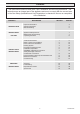
15 Spare Parts When ordering spare parts, contact Glow-worm’s own service organisation using the telephone number on the front cover of this booklet. Please quote the name of the appliance and serial number, to be found on the data label, see diagram 1.2. If ordering from British Gas also quote the G.C. number of the part. Key No. Part No. Description GC Part No.